Calendar with cyclical variables
I wanted to create a calendar with replacable components so that I could use the same structure for tracking multiple things. The first idea I had was to have multiple movable circles held together, working similarly to a compass. I first made it out of carboard and laser cutting it.
PROTOYPE 1 : cardboard
The cardboard I used : 2.5mm
DESIGN IN FUSION
The cutting settings I used in Lightburn
speed: 80
power max: 75
power min: 20
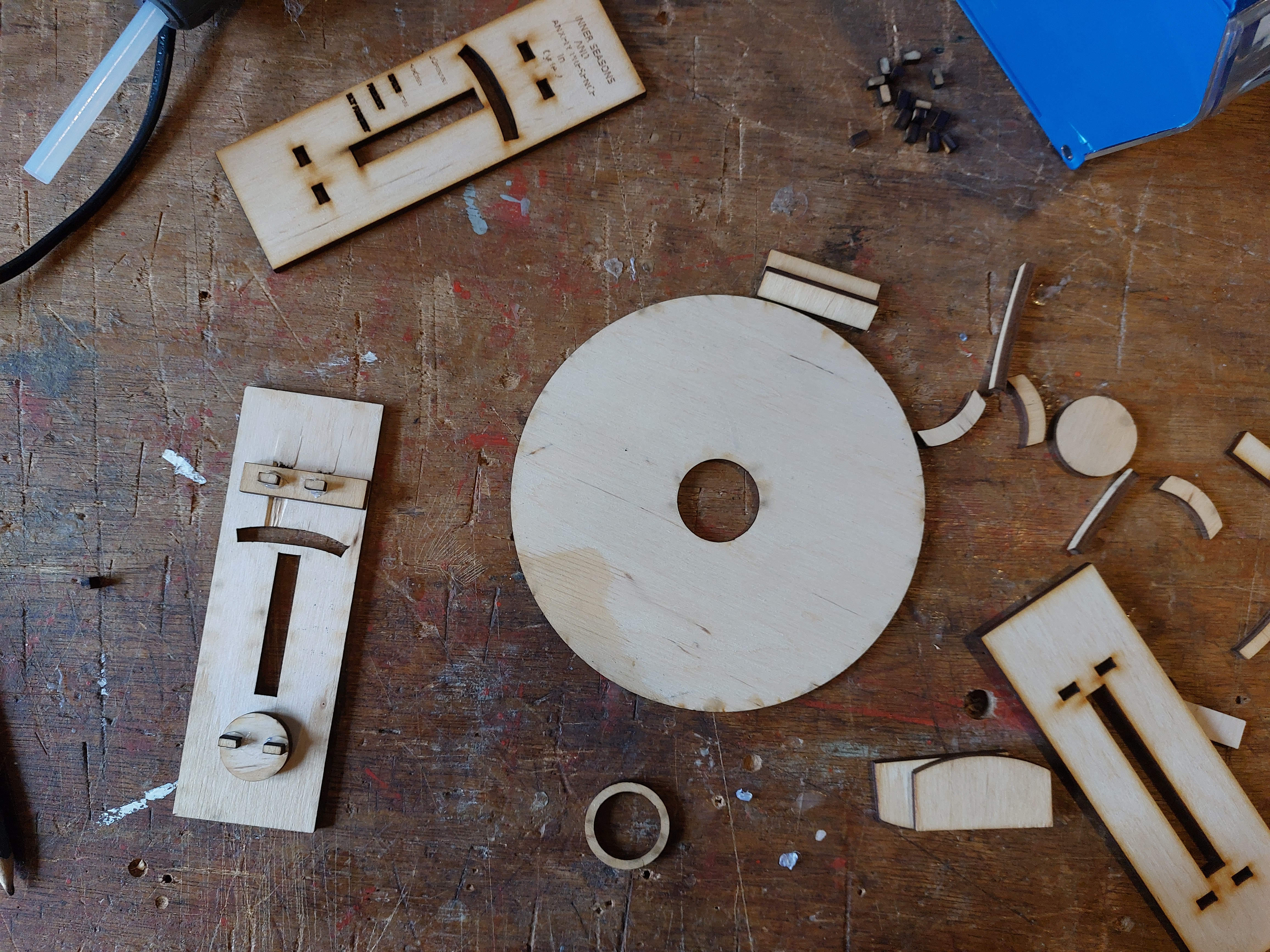
This shows one side of the base structure, with the circles held in place by supportive arcs glued to the base. It was all pretty sturdy, except for the teeth of the pressfit middle connection pieces. When I applied pressure to the teeth to press it into the holes on the base, they would crumble like below.

I then grabbed some scrap thicker cardboard and cut the teeth out of that instead. It looks similar to MDF in structure but is definitely still cardboard. It is luckily the same thickness. Below is what this looks like once glued to the middle connection base. : s40 p95 works for this material with the laser.

(pressfit connection pieces)

The structure was surprisingly sturdy, although not for long. The circles were able to move quite easily,so I felt I could keep the dimensions of them as well as the supporting arcs the same.
PROTOYPE 2 :
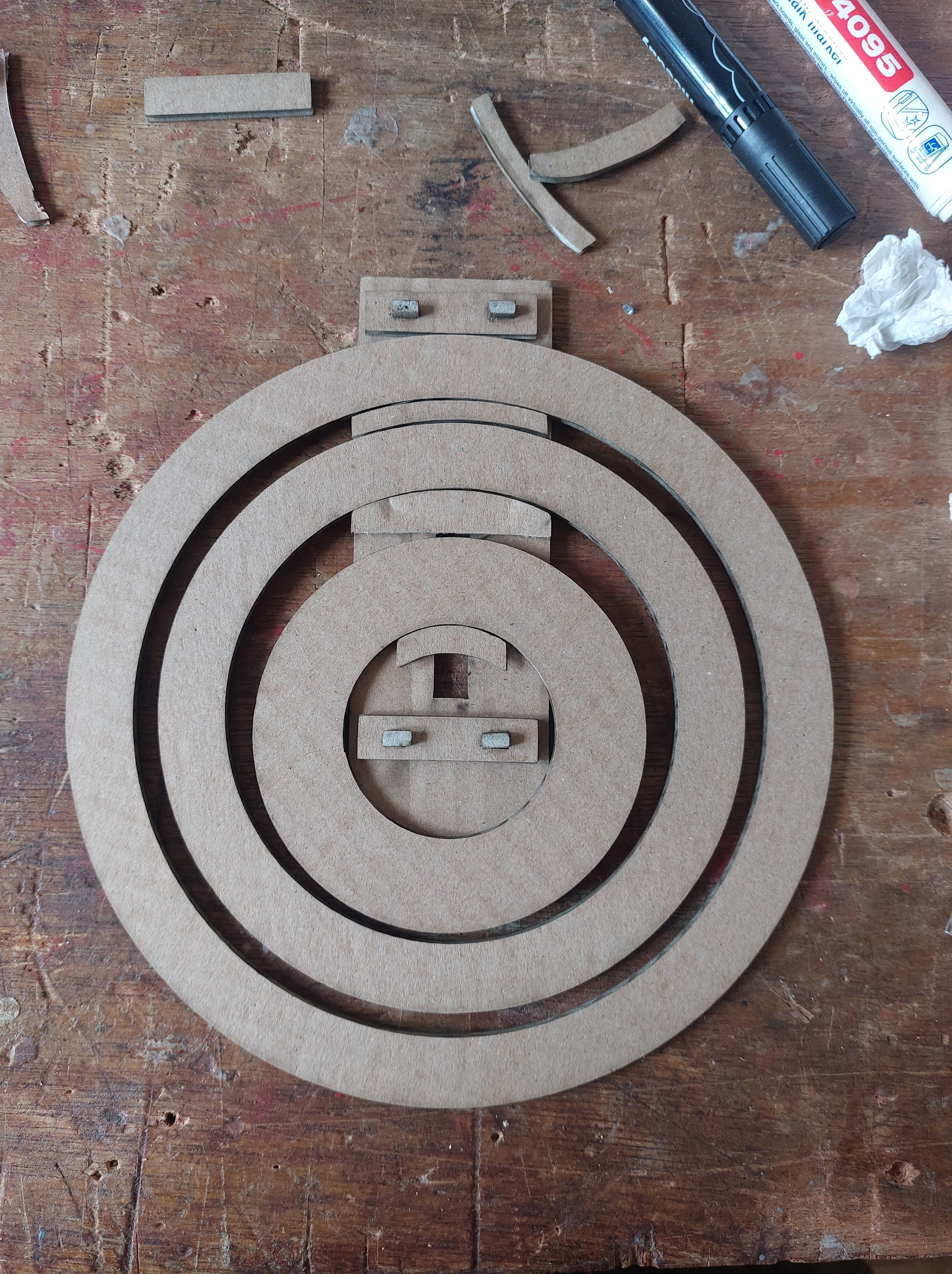
I made the two sides of the base slightly longer to be able to show more data, and wider so that certain parts wouldn’t be as fragile. I haven’t cut the circles out of wood yet, because I want to design the representation of data first so I can engrave on it right away. I used the cardboard versions to see if the dimensions still work.

I then used the graph I had made, more info on that here, and applied it to the structure in Illustrator.

-
And it moves really smoothly! The pressfit connections were initially really sturdy, but they gradually became not so sturdy. I wonder if these were thicker and therefore less prone to fall out of their pockets on the their base, it would work better. I could glue all of it together permanently, but I really want the components to be replacable and adaptable by the user, as well as easily assembled.
-
After a couple of days, some of the teeth on the pressfit middle connection broke off, and although it clicks together well it doesnt hold it long. I wonder if longer teeth would be helpful, or perhaps printing it out of filament so the teeth and base are one component.
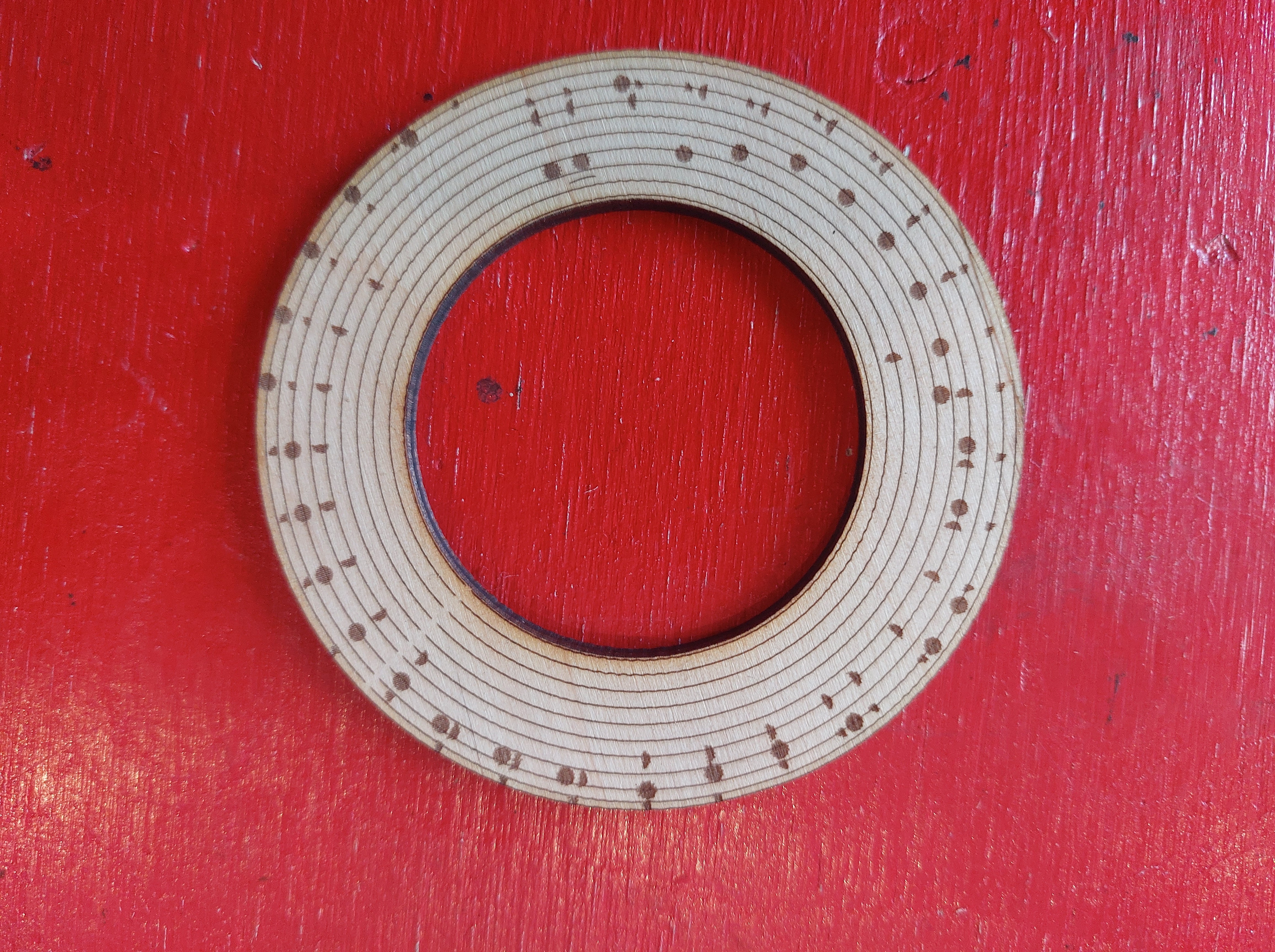
Engraving settings:
- The engraving did not turn out well. I tried a couple of different ratios between power and speed for the text, but the outcome also kept changing. A couple of days later the laser lens was cleaned and turned out it was really dirty, so perhaps that was the problem. I also looked at some pieces the other intern Maria had done with text engraving, and in image mode text came out really nicely. I might try that instead of fill or line mode.
- The circles engraved are also quite irregular, perhaps the speed was too high for the laser to manage.
View Our lasercutter page for more information on settings and options
PROTOTYPE 3: The cycle watch/bracelet
ITERATION 1
I want to make the calendar wearable, and therefore more compact and sturdy. I am building off of the previous designs. Because I am going to be 3d printing and lasercutting components that need to fit together, I need a clearer work flow so that measurements don’t get lost along the way.
- Design the structure in Fusion 360
- Export lasercutting components as dxf _ Export 3d components as obj/stl
- Import finished dxf design to Illustrator, and apply graphics
- Import obj/stl to slicer for printer
- 3d print components
- lasercut components
- assemble
DON’T GO BACK AND FORTH!! (you screw yourself over ella)
- Any necessary adaptations
- Choose material to lasercut and if needed go into fusion to adapt parameter
-
3d printed middle connection piece outcome compare to bolts
- go back to fusion to make needed changes
GOOD TO KNOW
In fusion360, if you copy and paste a component it will automatically stay linked to the origin component. So if you make changes this will directly do so to the origin component as well. In order to avoid this, When pasting. choose PASTE NEW.
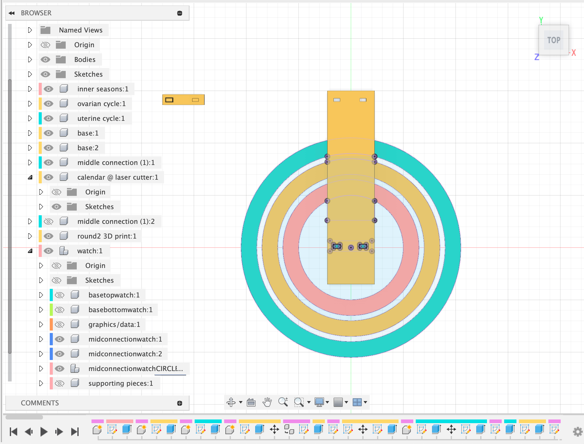
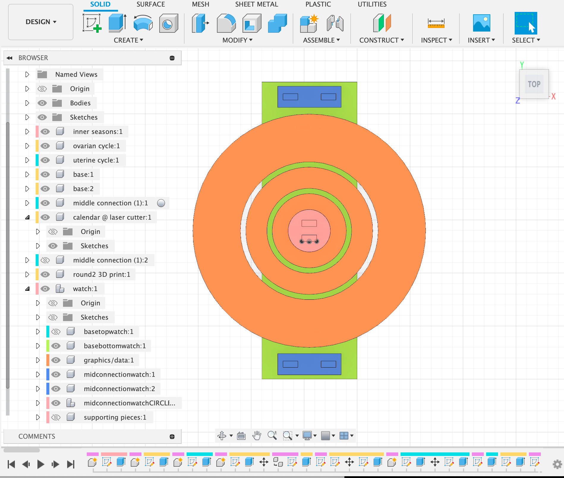
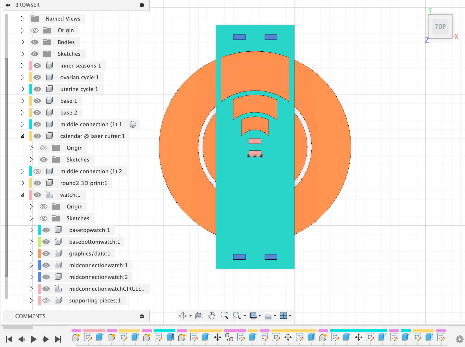
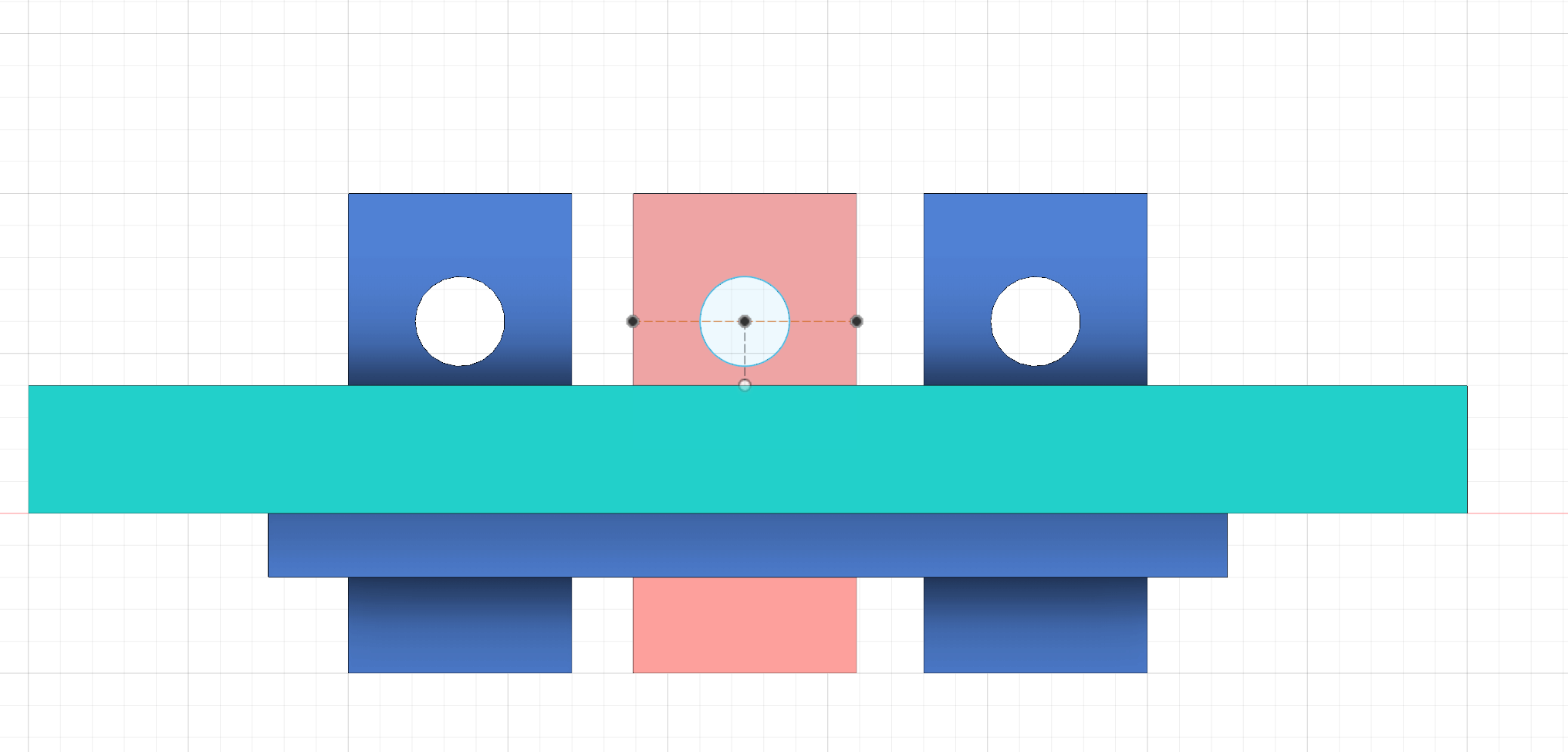
DESIGN THE STRUCTURE IN FUSION 360
 without top base
 with top base
-
I made a couple of parameters: offset of joint for middle pressfit connection thickness of wood for lasercutting diameter of hole for bolts
-
Next time I do this, however, I will make the whole design parametrically put together. This will make it a lot easier to make small changes as well as work towards the larger picture of my project which is for these tools to be adaptable for different people.
EXPORT LASERCUTTING COMPONENTS AS DXF
- I created a new component with sketches that hold projections of all faces I need to lasercut. with top base
EXPORT 3D COMPONENTS AS OBJ/STL
top connection base to base middle connection base to base bottom connection base to base
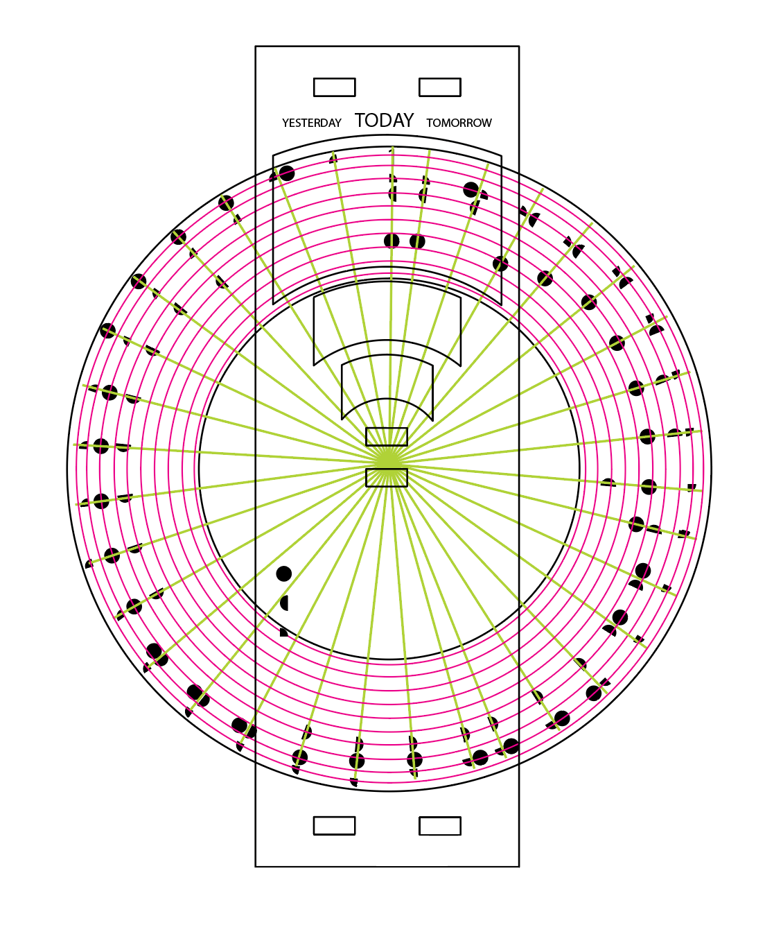
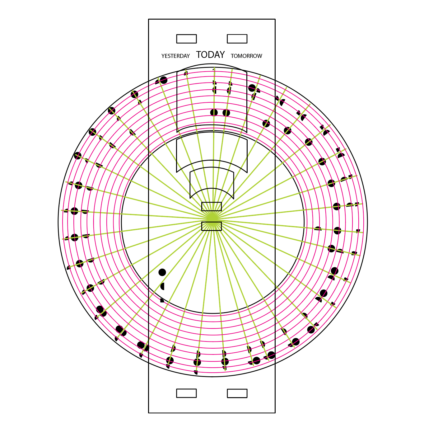
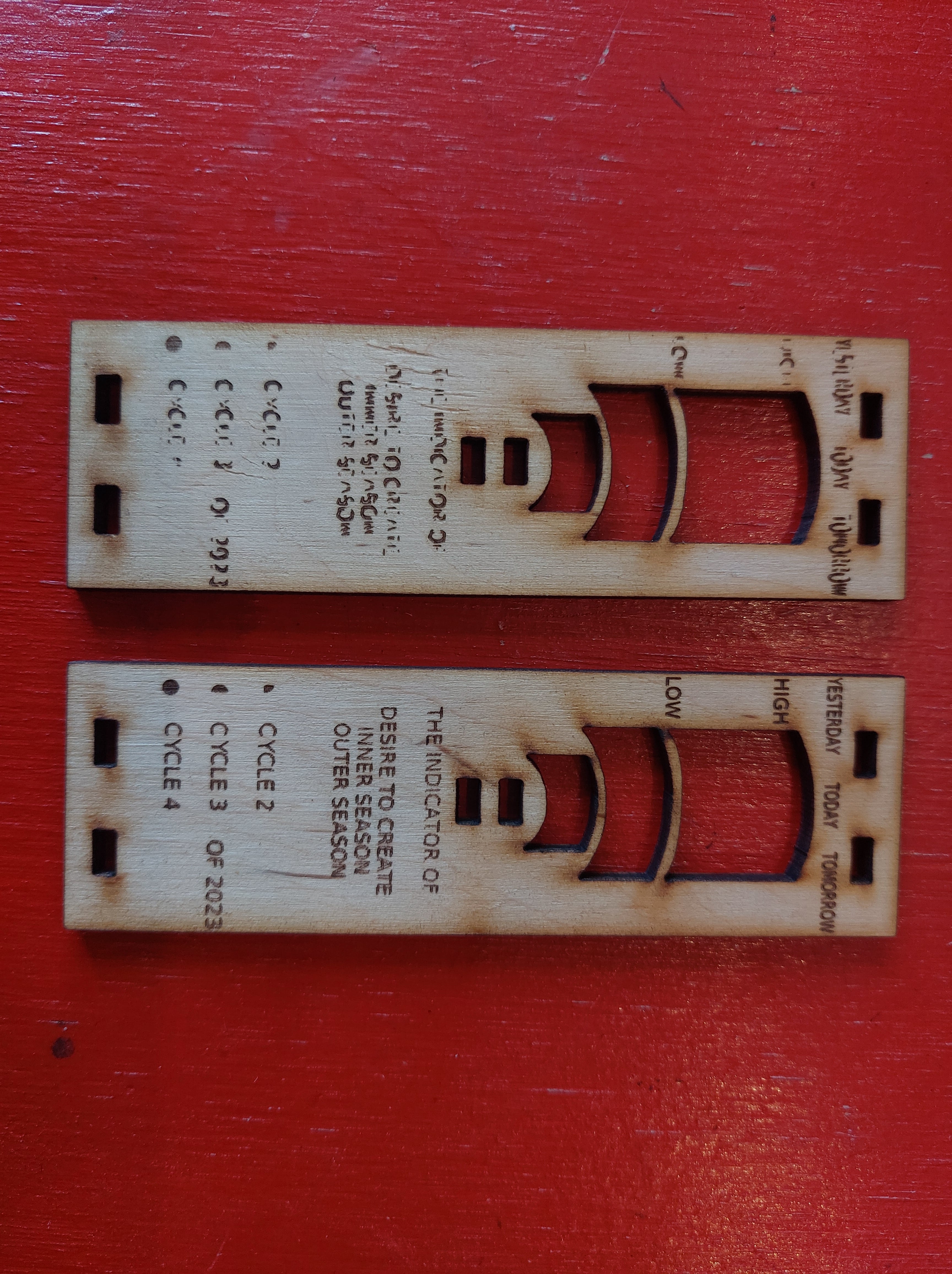
IMPORT FINISHED DXF DESIGN TO ILLUSTRATOR AND APPLY GRAPHICS
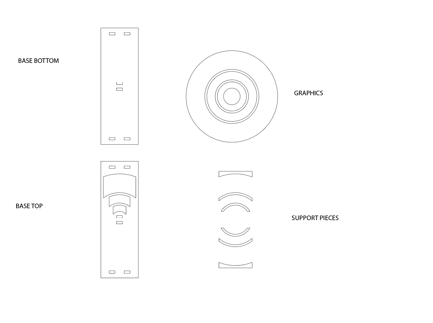 imported
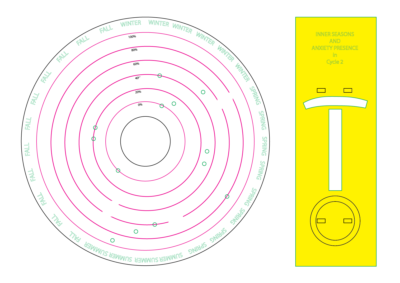
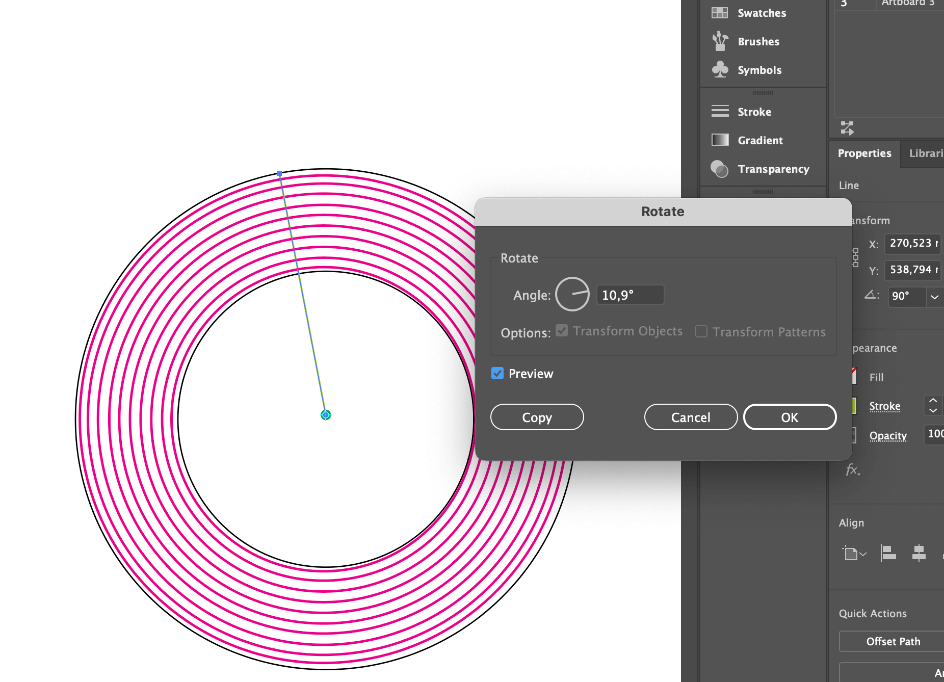 creating the structure for data plotting
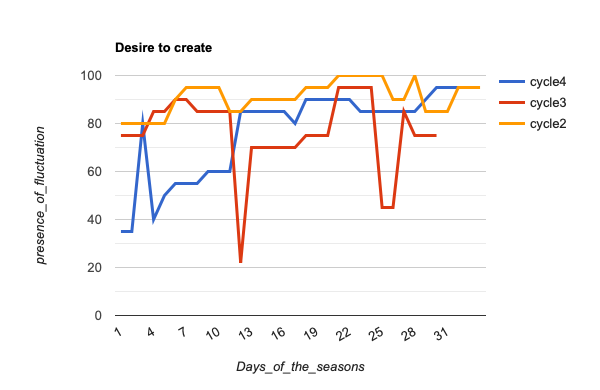
creating graphs out of my collected data of cycles 2, 3, and 4 of the year 2023
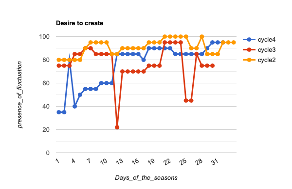 cycles 2, 3, and 4 of 2023
 design to create
- This time around I am using data from three separate cycles, the longest one being 33 days. That is why this iteration has 33 data points.
Instead of calculating a medium or mean from these three data groups, which is what I was planning, I decided to represent all of them to show the range in which these cycles can come to be. This is also more accurate to the experience of this specific fluctuation, instead of framing it in a linear manner.
- Making slight adjustments to the base so it aligns with the graphics
 do not match
 do match
ANY NECESSARY ADAPTATIONS
- Material thickness of wood for lasercutting: 4mm
-
mid connection piece socket way too small for bolt
- Went back to Fusion360 and:
- realized it didnt make it match the bolt so adapted the parameters
- extruded the connection pieces 2mm more
- exported one as a test
- back into slicer
more information is on my 3d components page.
 in fusion360, holes adapted
3D printing components
page on process of 3D printing components
Lasercut components

I did a couple of tests with different engraving settings before cutting components. I found that the image mode did not come out well at all, so I ended up doing line engraving in both fill mode and line mode
SETTINGS USED:
CUTTING
Speed : 40 Power : 100
ENGRAVING LINE
Speed: 25 Power : 10
(took extremely long, could heighten both power and speed)
ENGRAVING FILL
Speed : 150 Power : 10
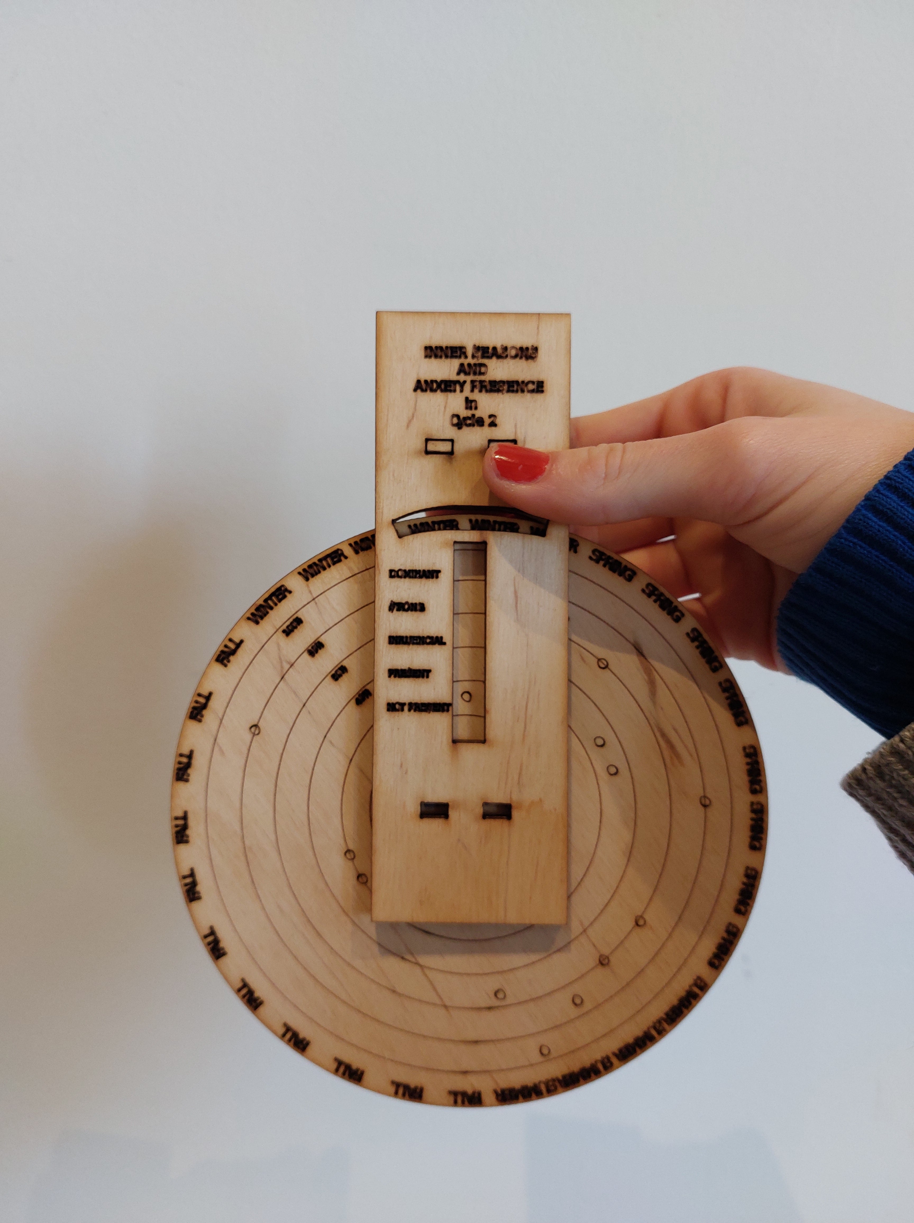
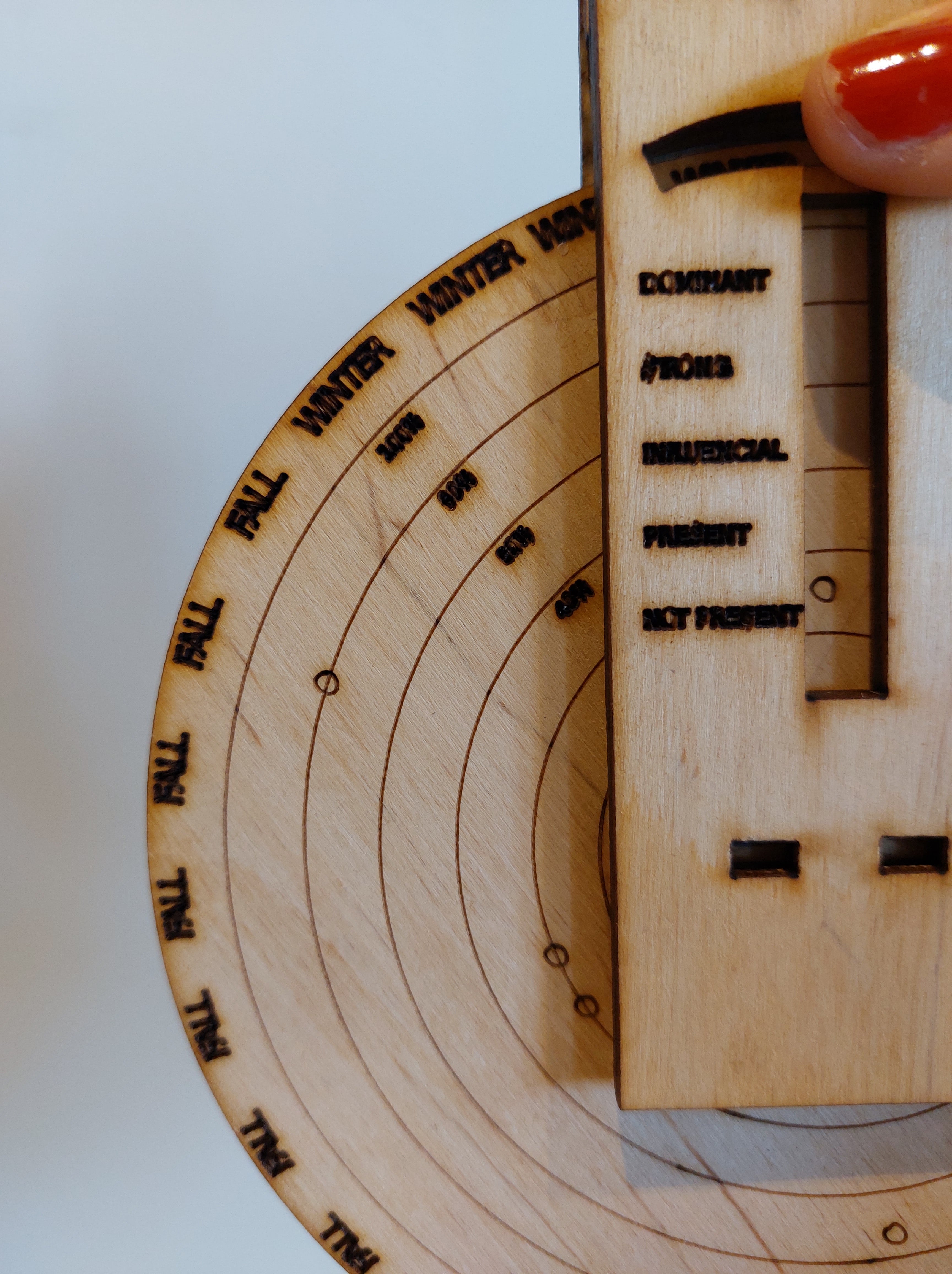
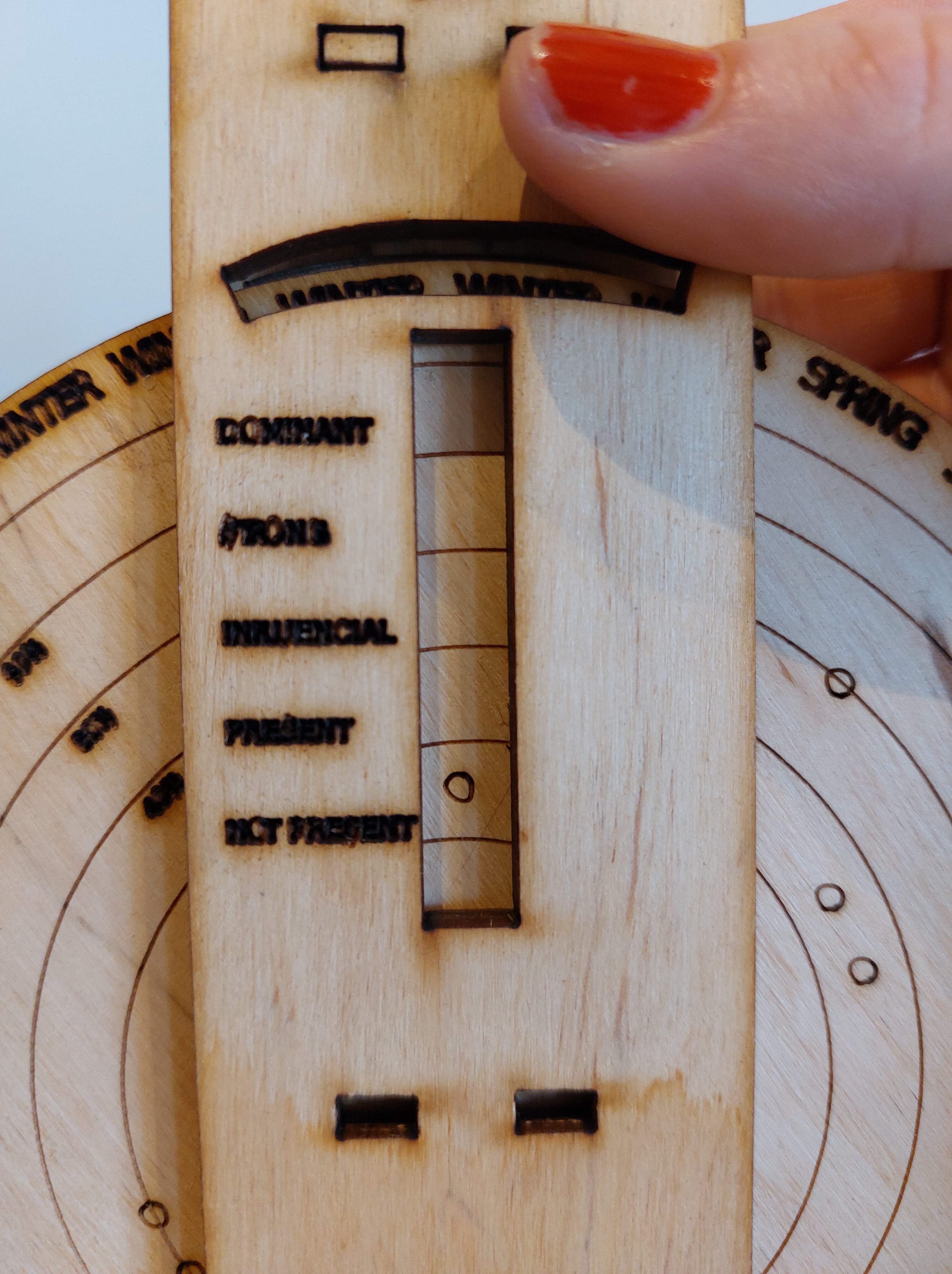
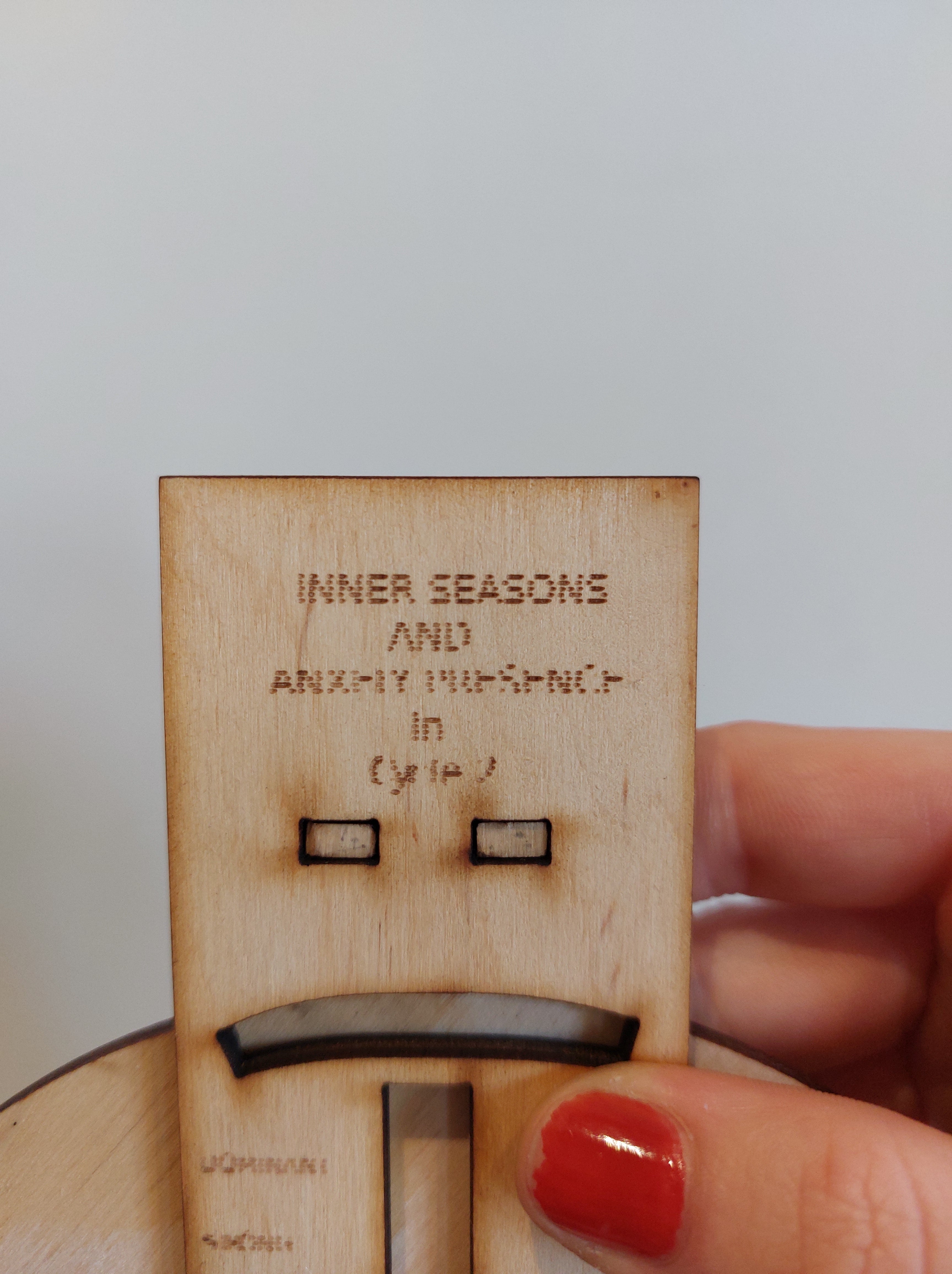
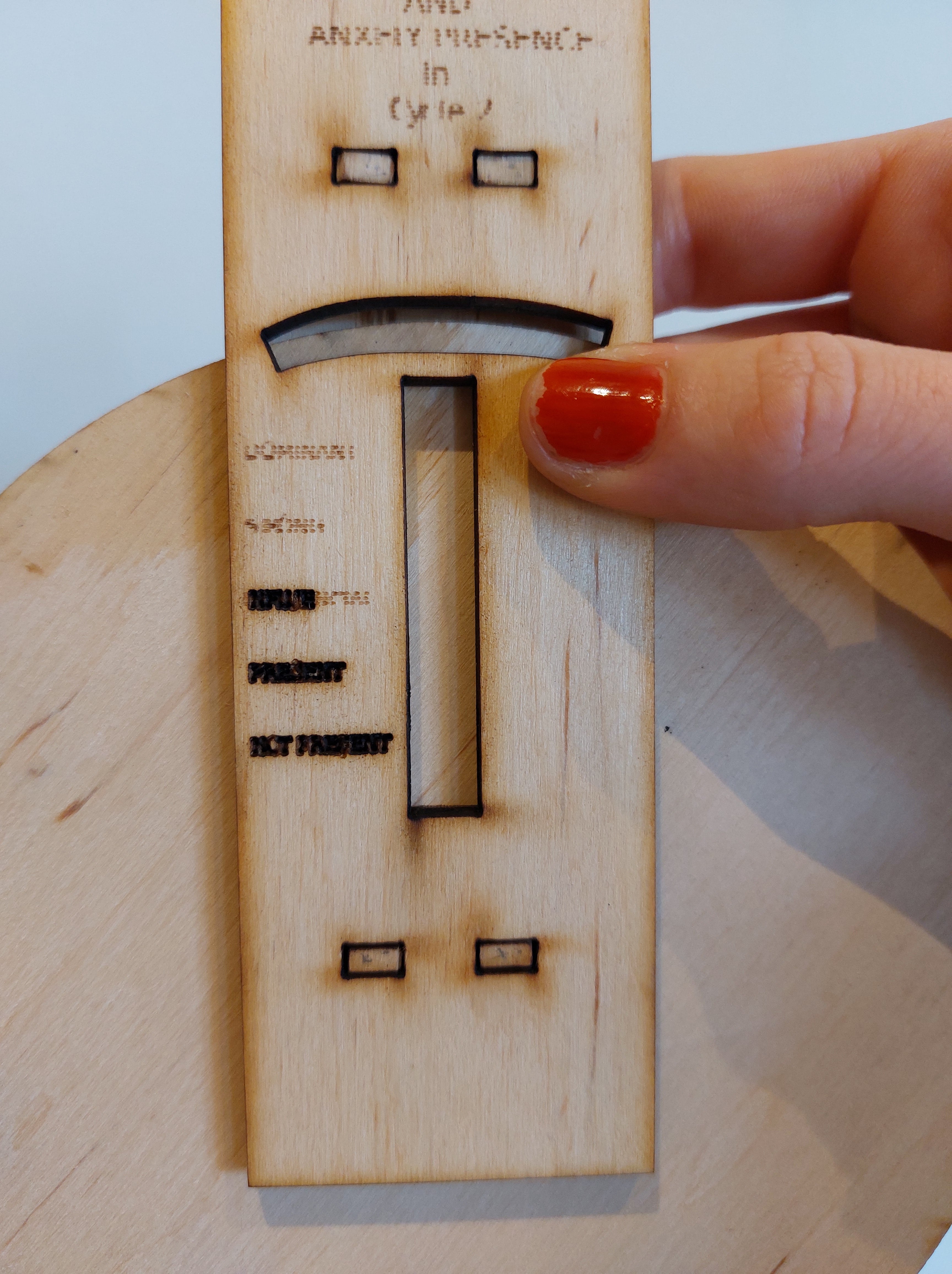
data plotter
front base
On the left you see the line engraving, and it started acting super strange. I am still not sure why, but I changed it to fill mode and kept the S/P the same, and on the right shows that outcome.
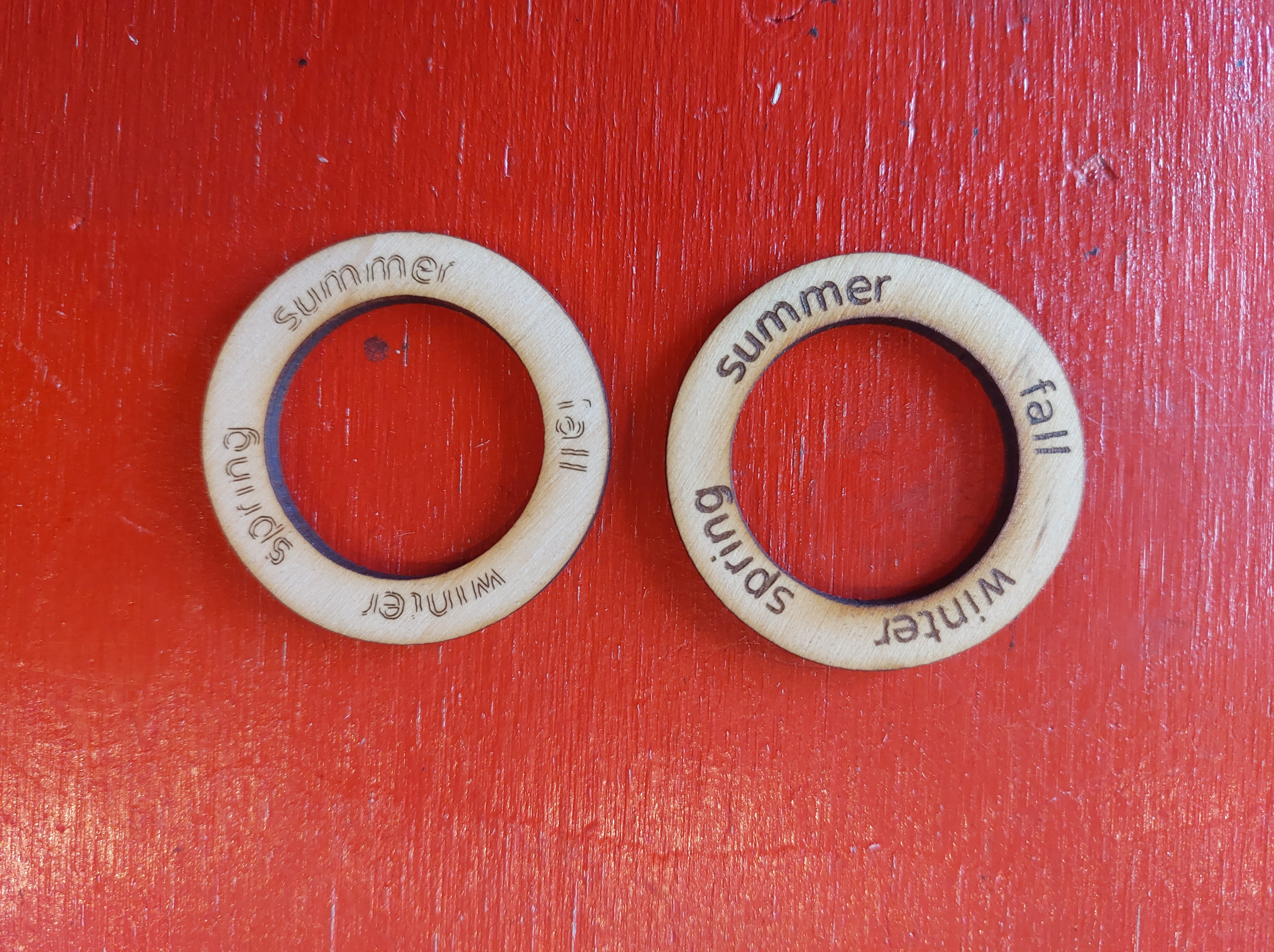
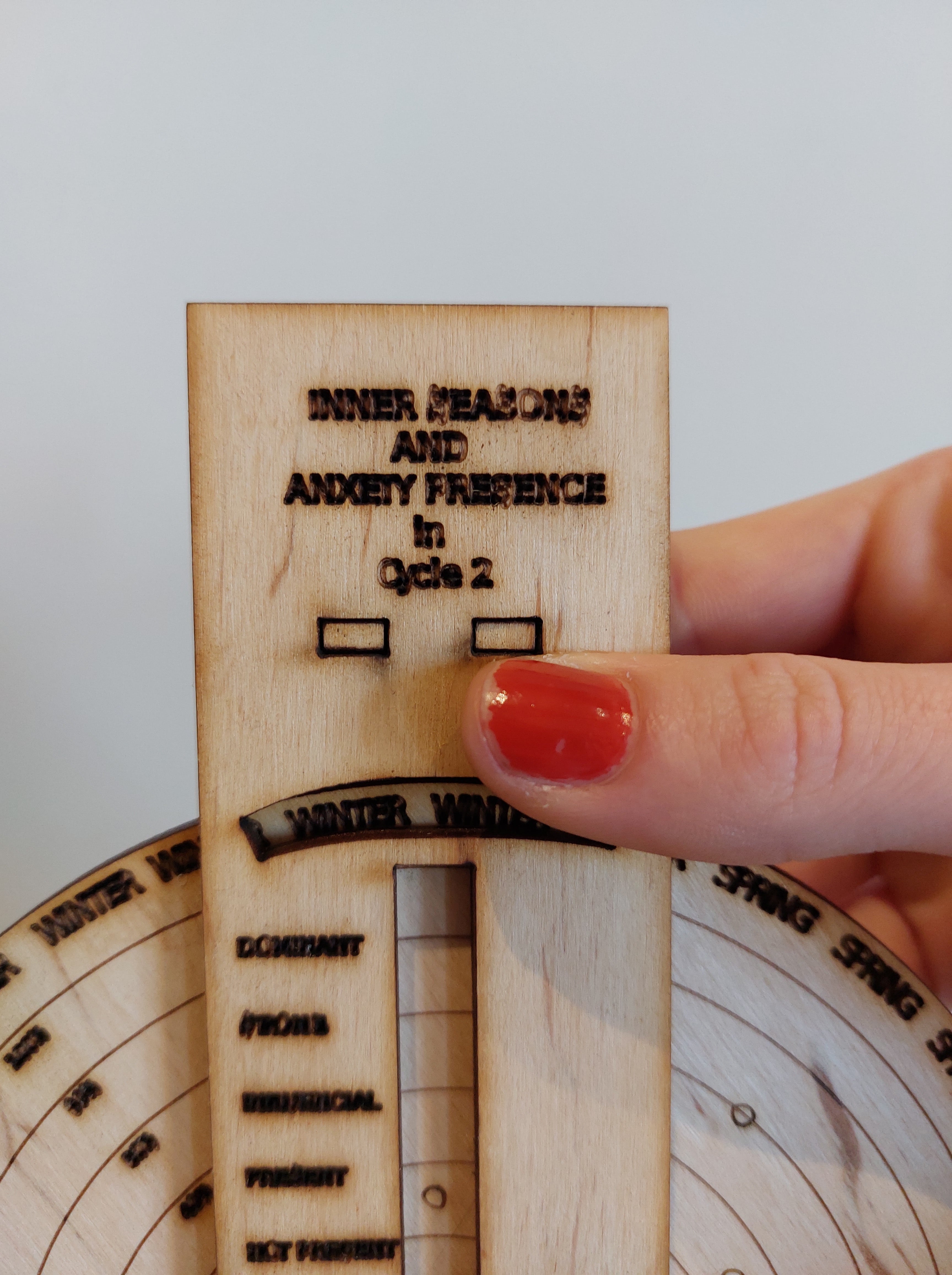
inner seasons cycle
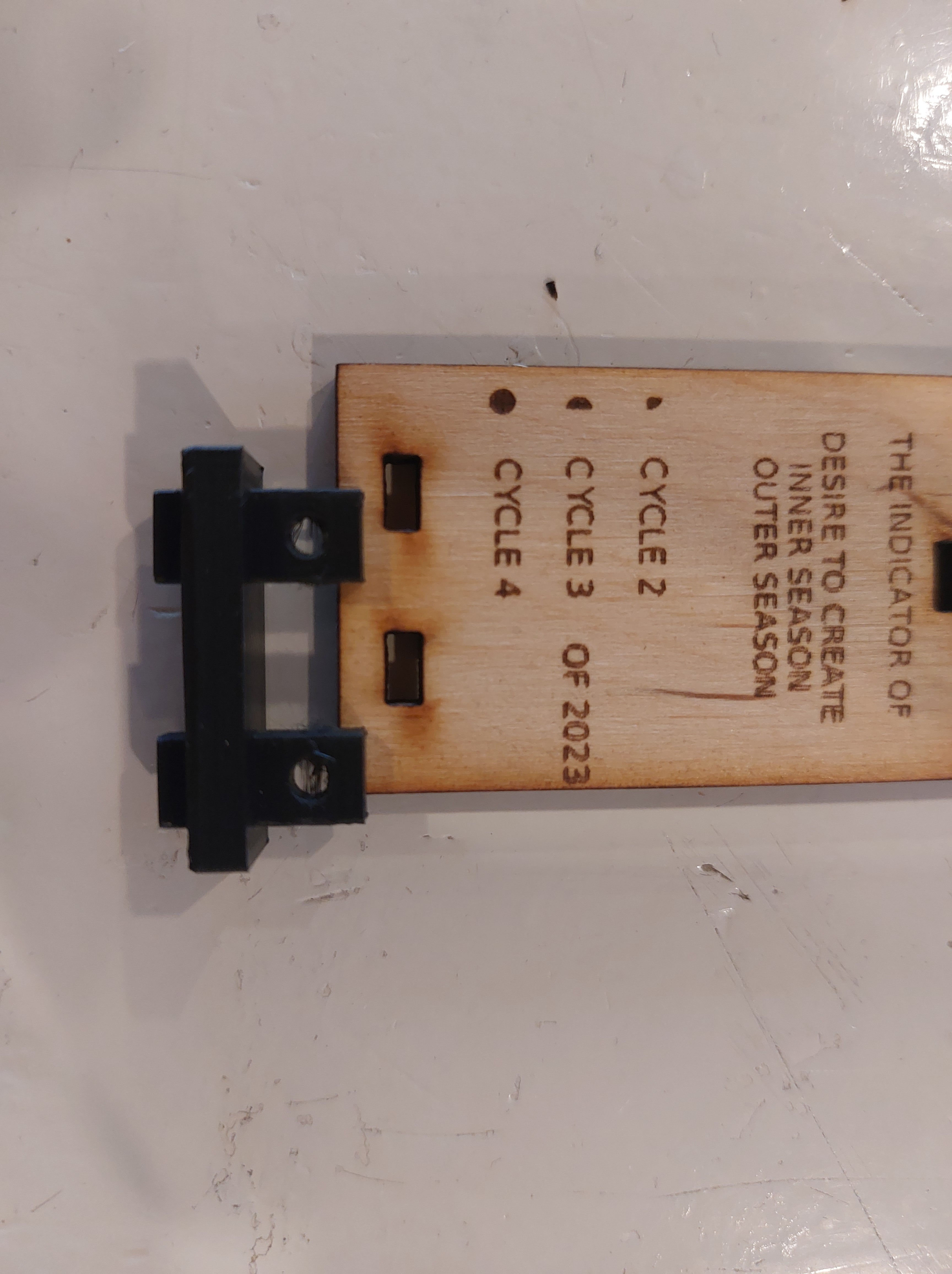
ASSEMBLING
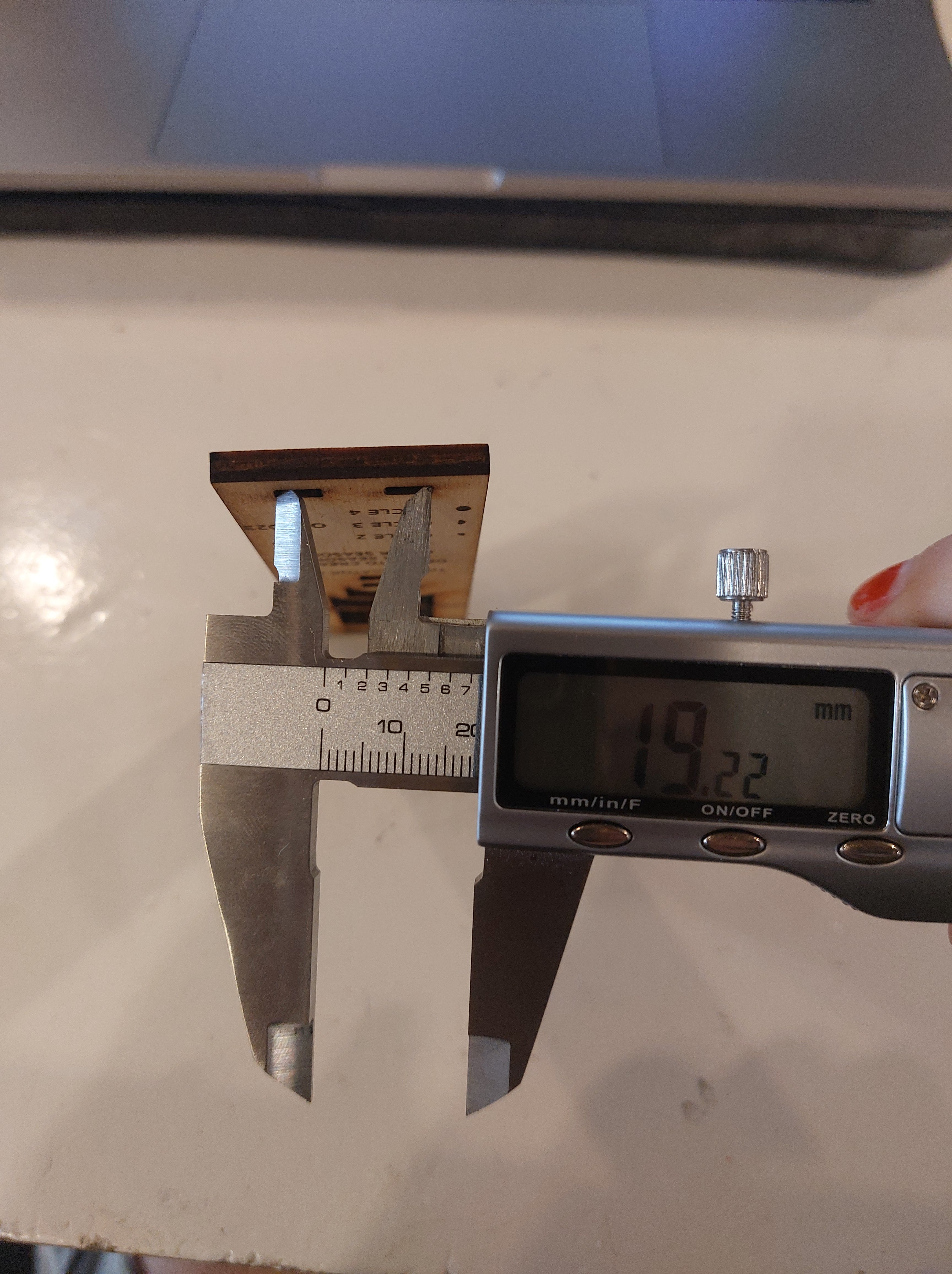
- When comparing the sockets to the finger joints on the 3d printed component, multiple elements were off: the size of the finger the distance between the fingers
 in fusion360, holes adapted
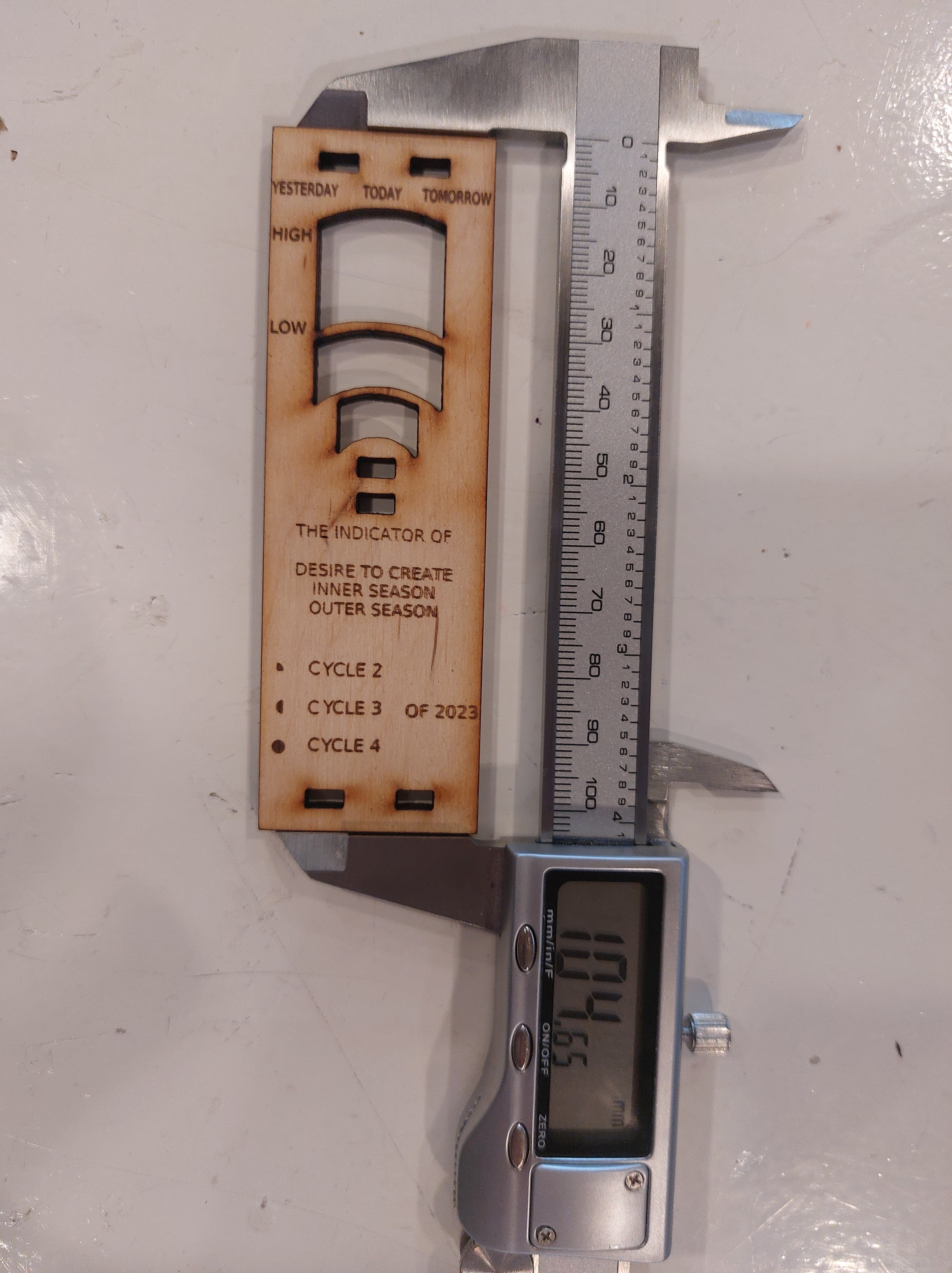
checking dimensions of components to find where the mis sizing is coming from
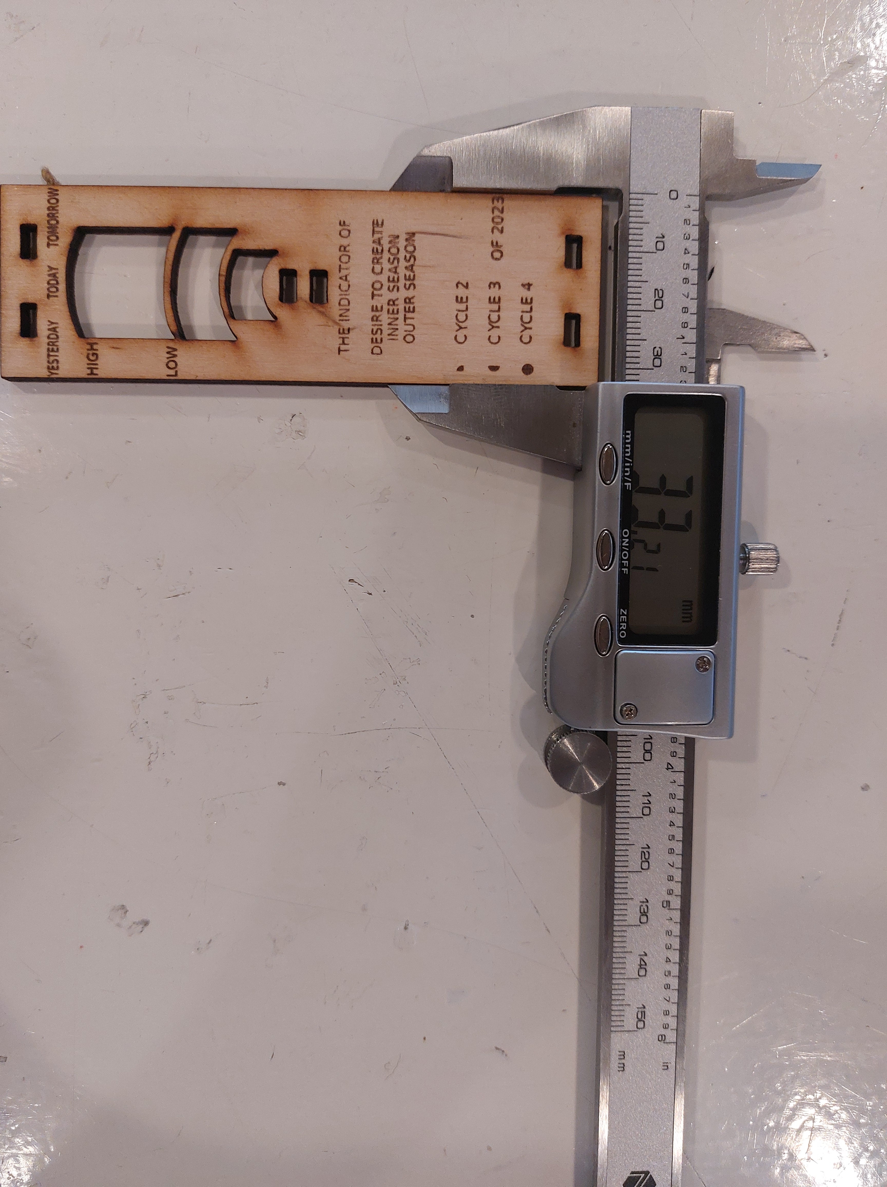
 physical
width in fusion360 is 45mm
length in fusion360 is 140mm
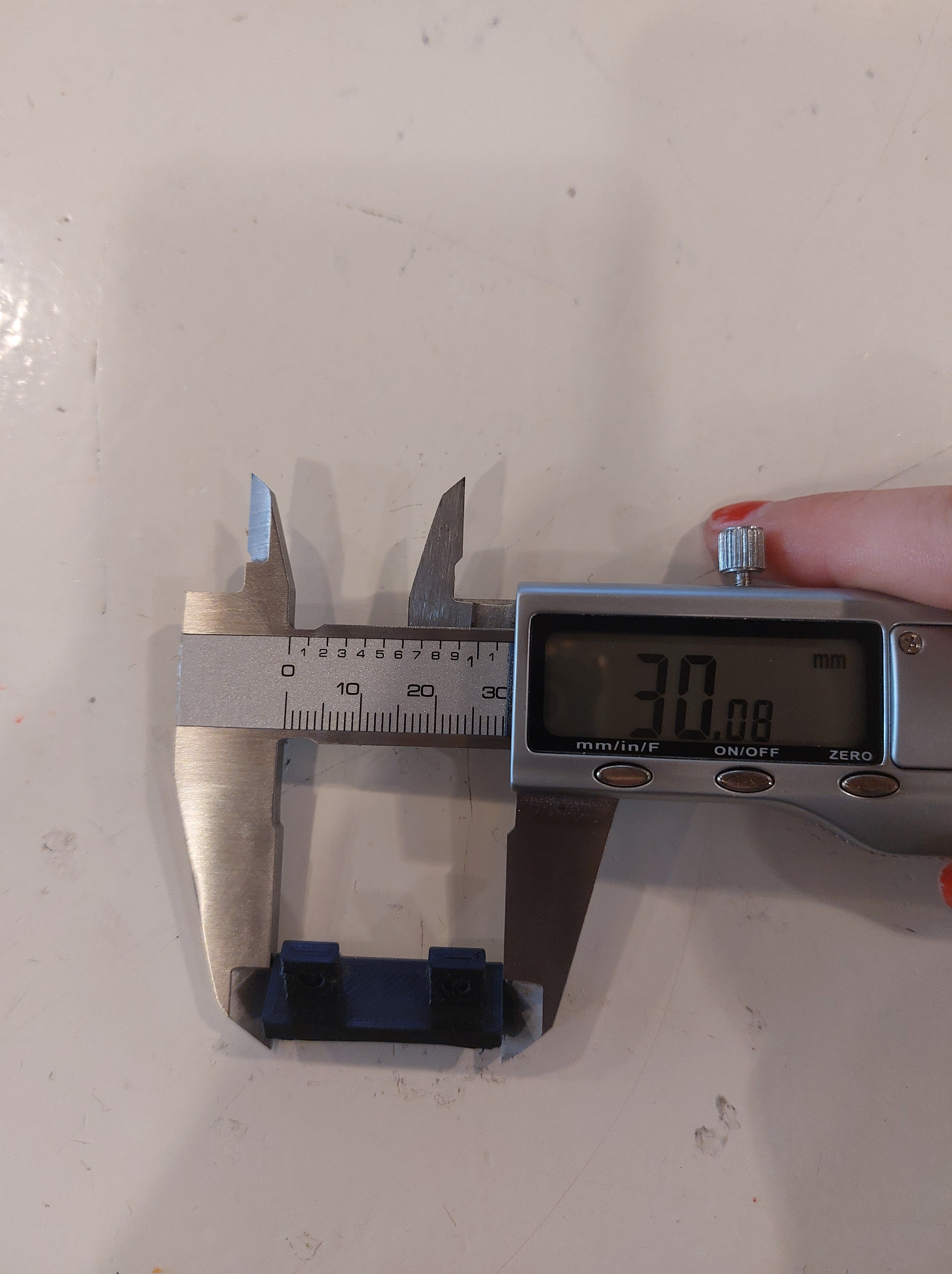 in fusion360 its 30mm
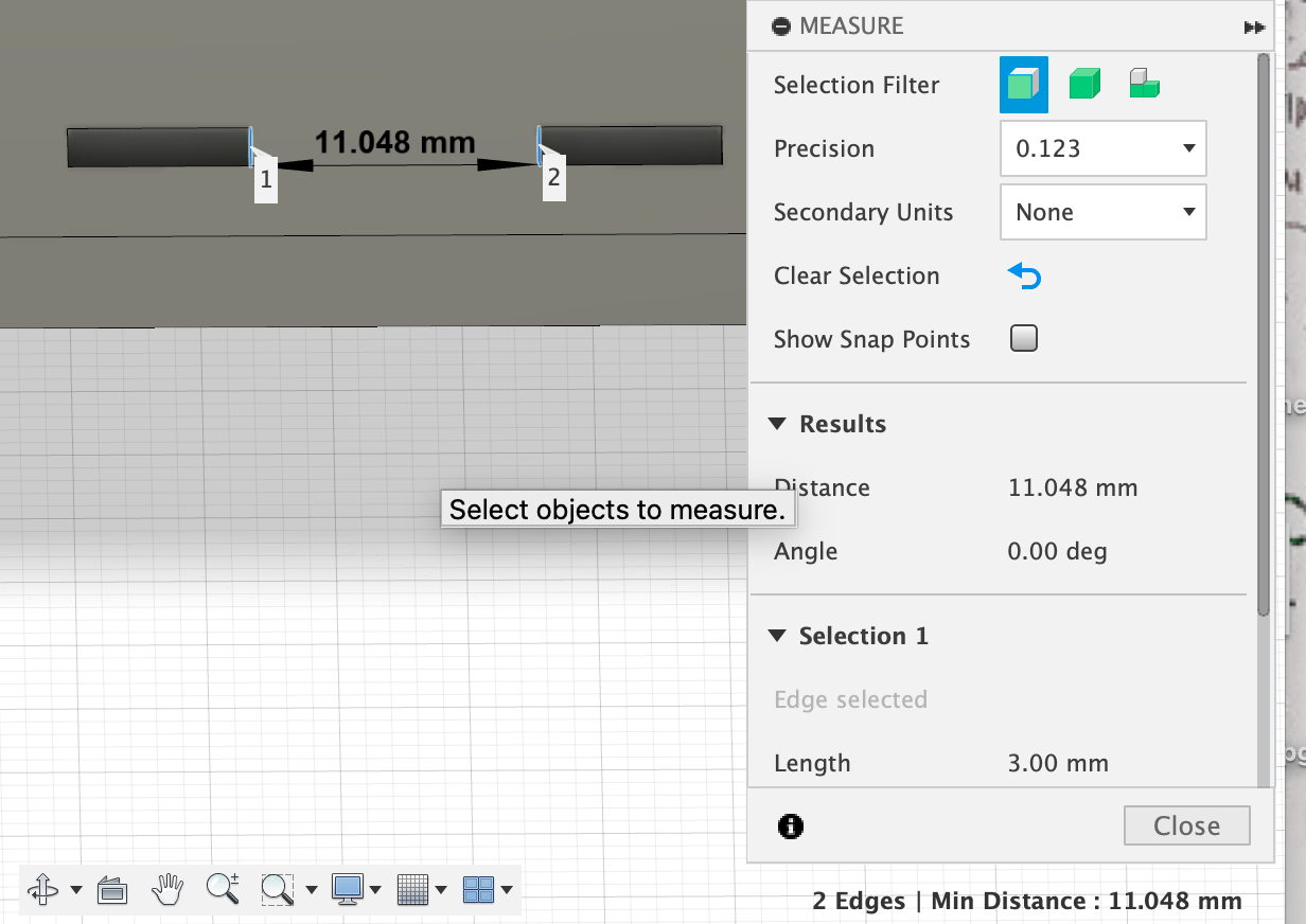
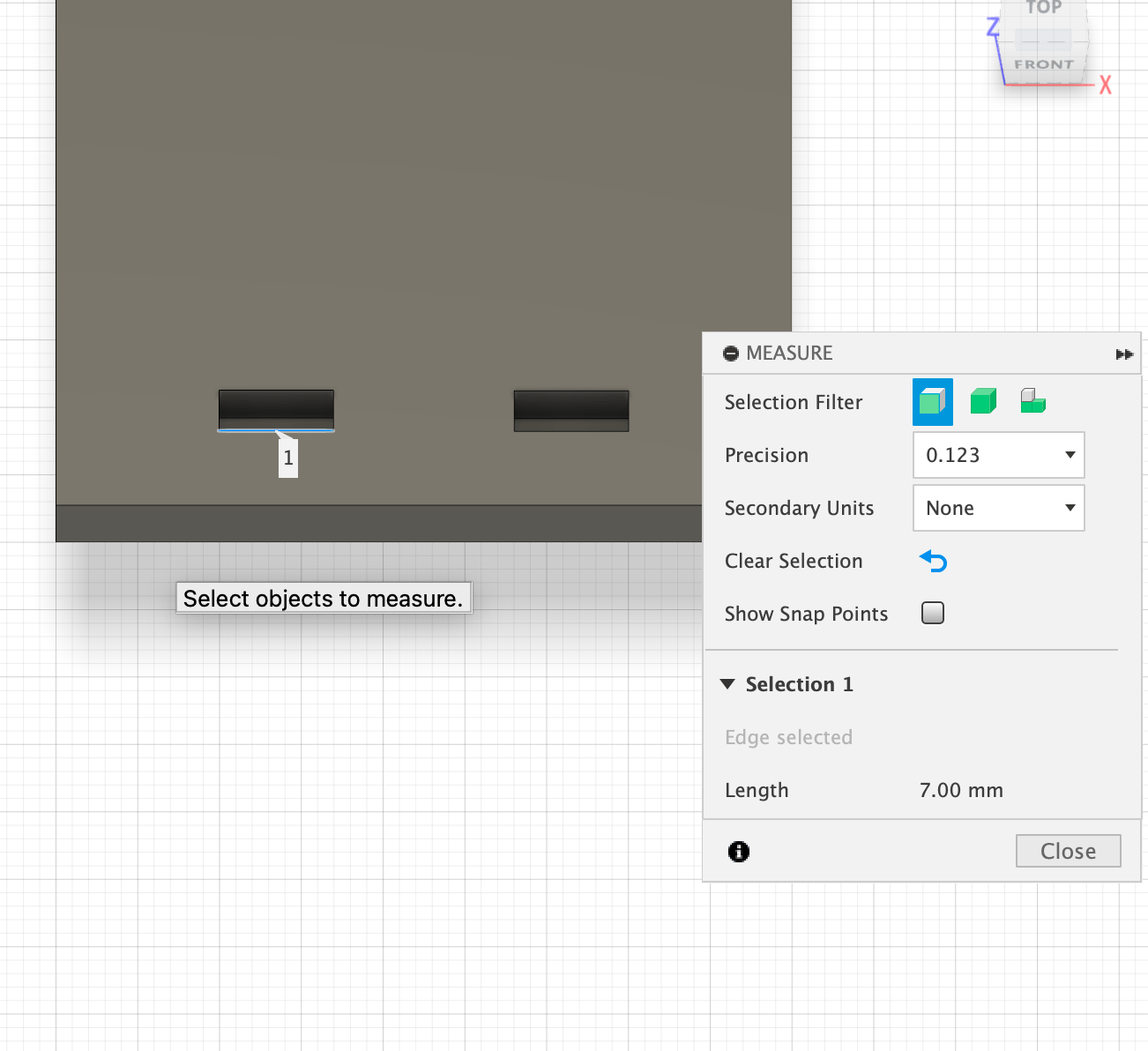
Lasercut sockets
between the sockets:
 in fusion360
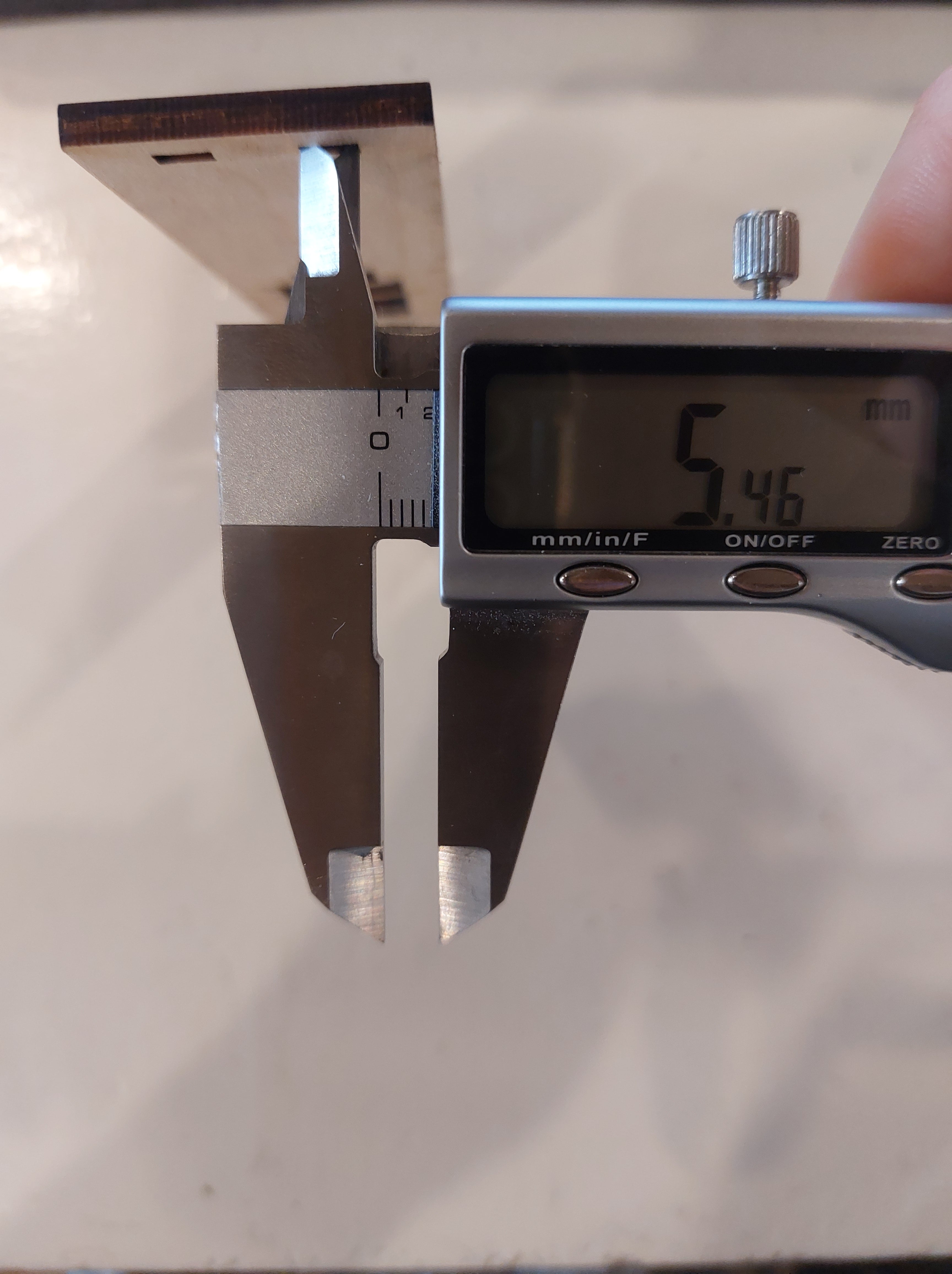
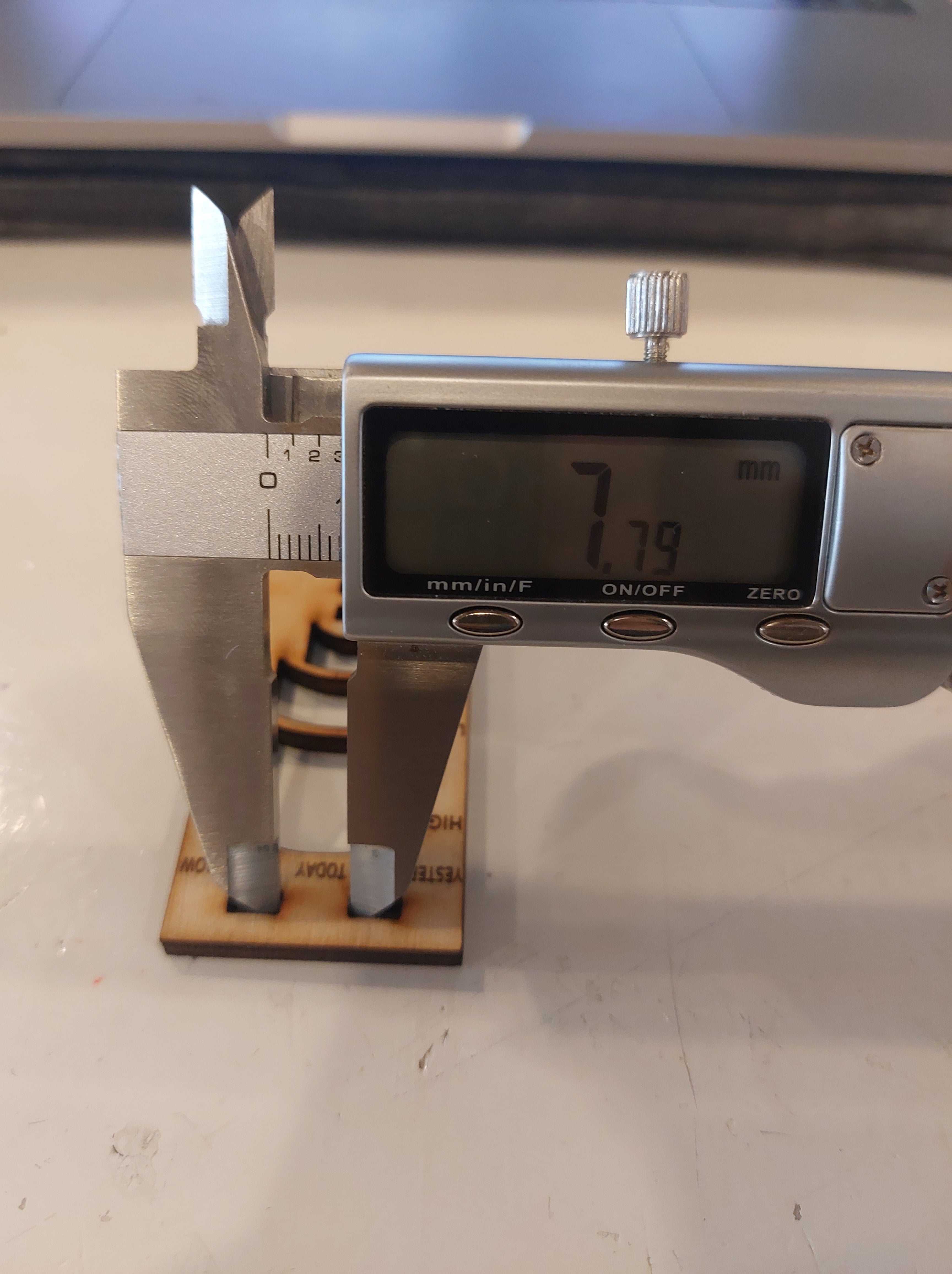
3d printed fingers
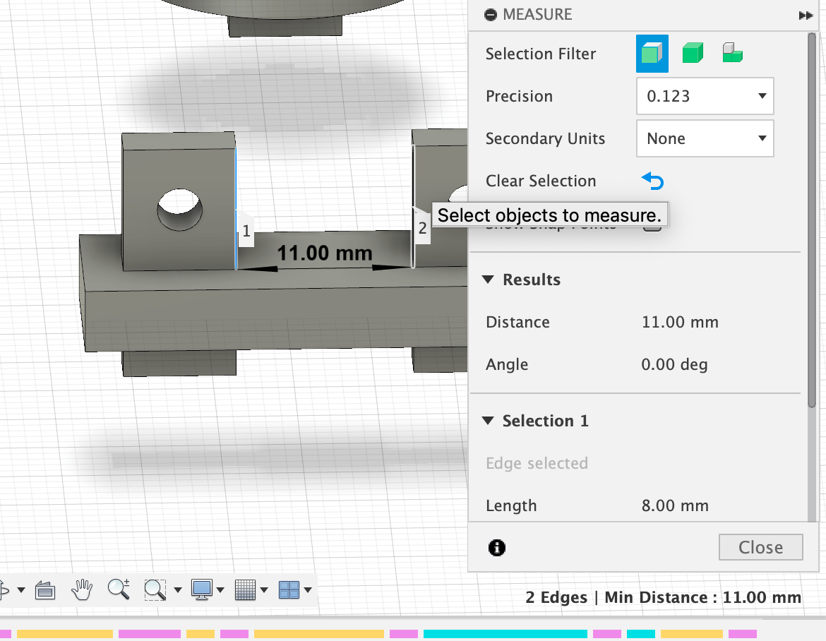
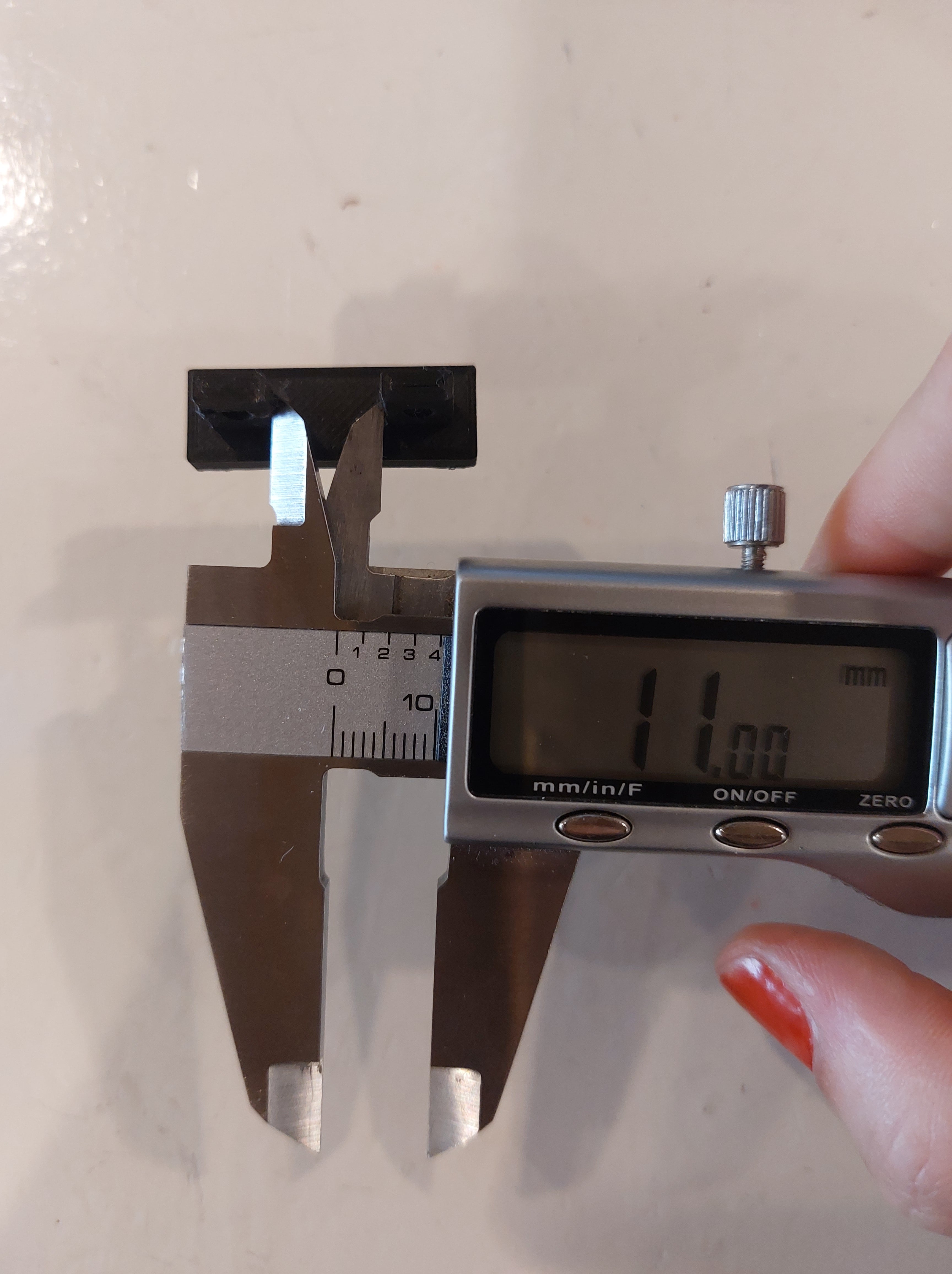
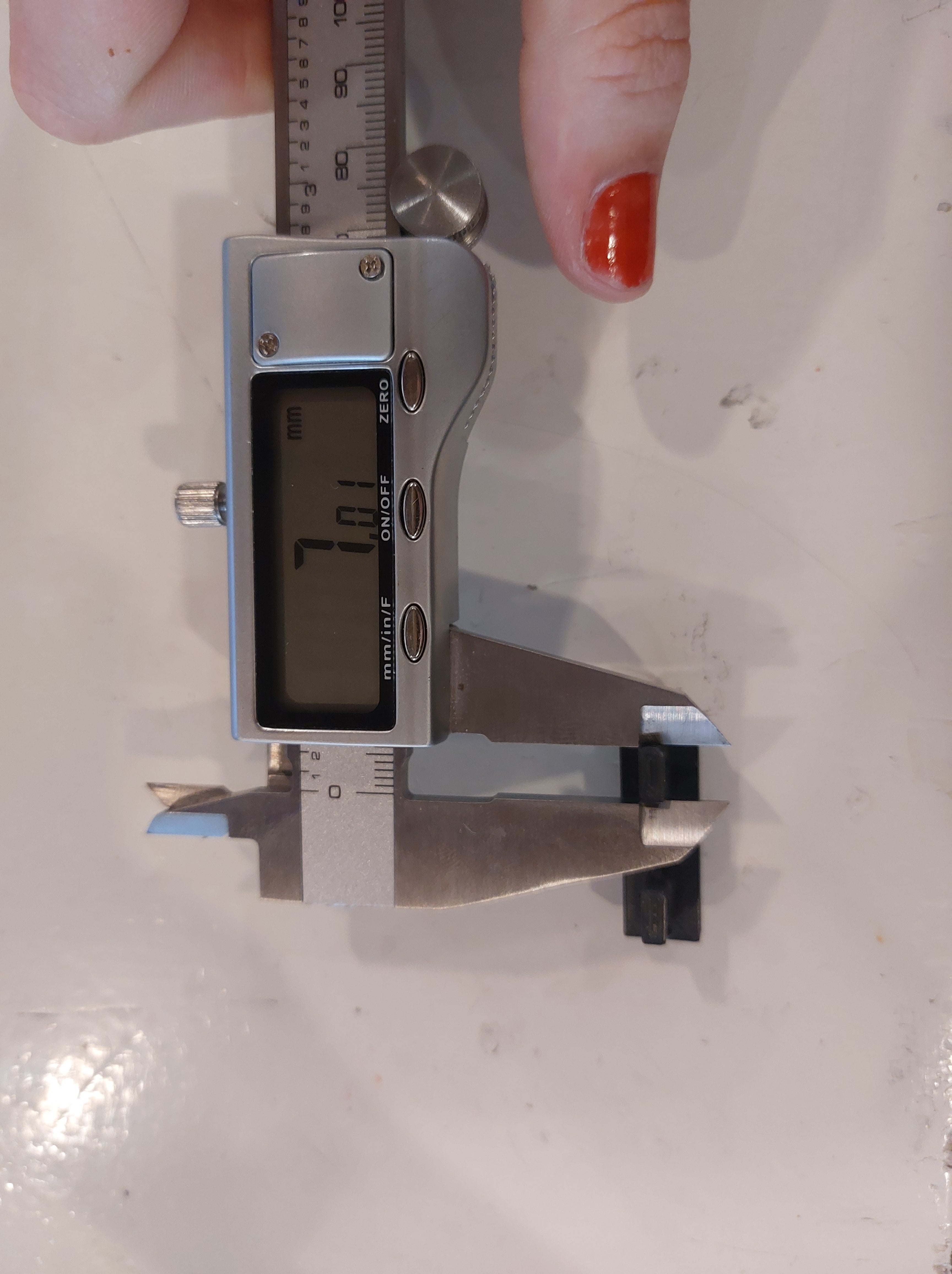 in fusion it is 7mm
CONCLUSION
So it is clearly the lasercut base that scaled somewhere along the way. Next time I know to check within each new software at least one of the dimensions so that I know something hasn’t accidentally been resized. I first thought it was Kerf but I don’t believe it would’ve led to such a different outcome.
- I went into Lightburn and scaled it up to the original dimensions.
image of front base in correct dimensions
image of front base and 3d midconnection piece
They fit! The hole for the bolt is too low, I think the material is slightly thicker than 4mm.
RESEARCH ON DATA HORMONES
https://www.ncbi.nlm.nih.gov/books/NBK279054/#:~:text=Estrogen%20levels%20rise%20and%20fall,end%20of%20the%20menstrual%20cycle.
https://womeninbalance.org/about-hormone-imbalance/
https://www.news-medical.net/health/Estradiol-Measurement.aspx