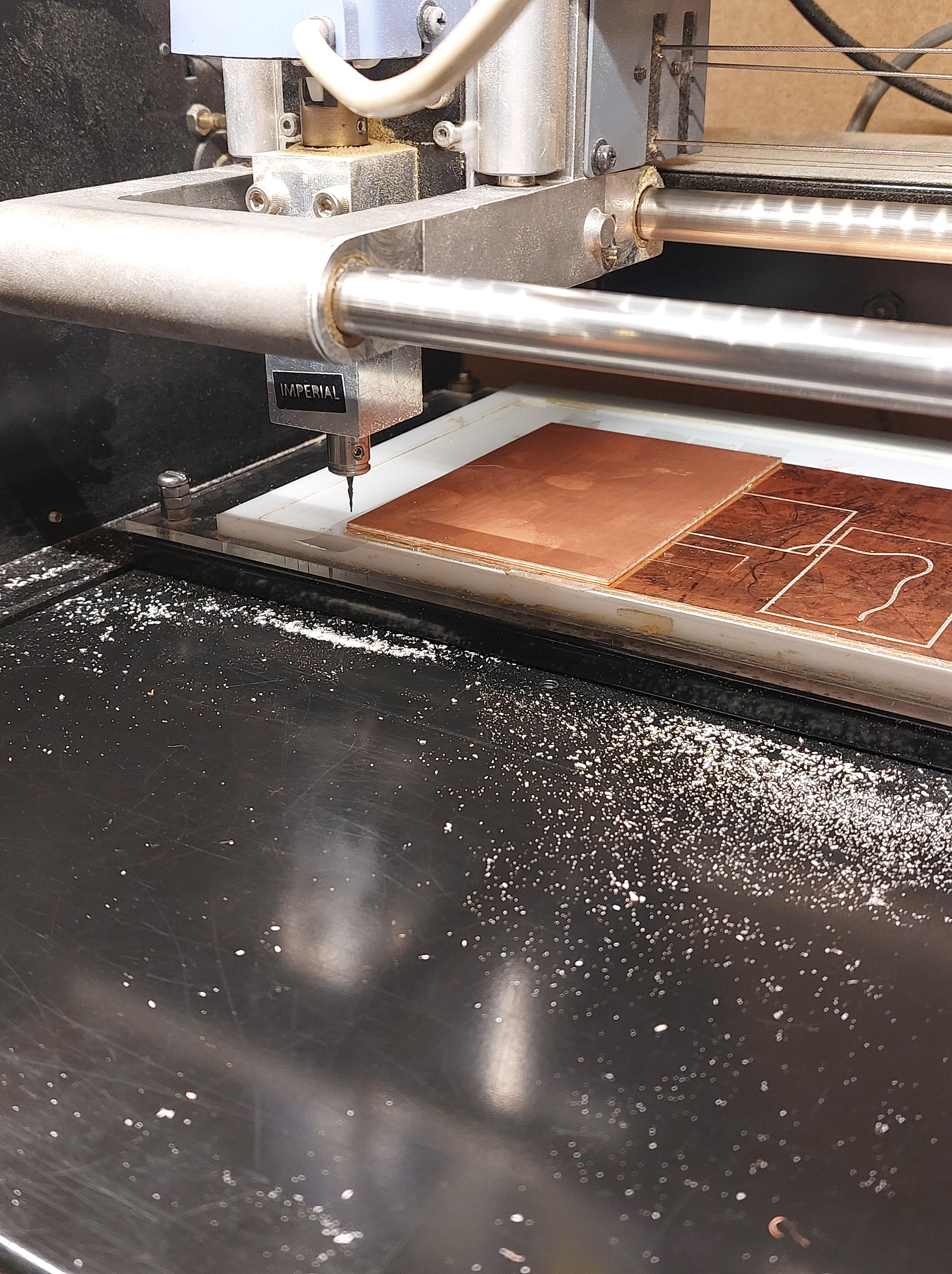
WORKING WITH
Our PCB milling machine: Modela MDX 20
Uses:
: making a printed circuit board from your digitally designed circuit
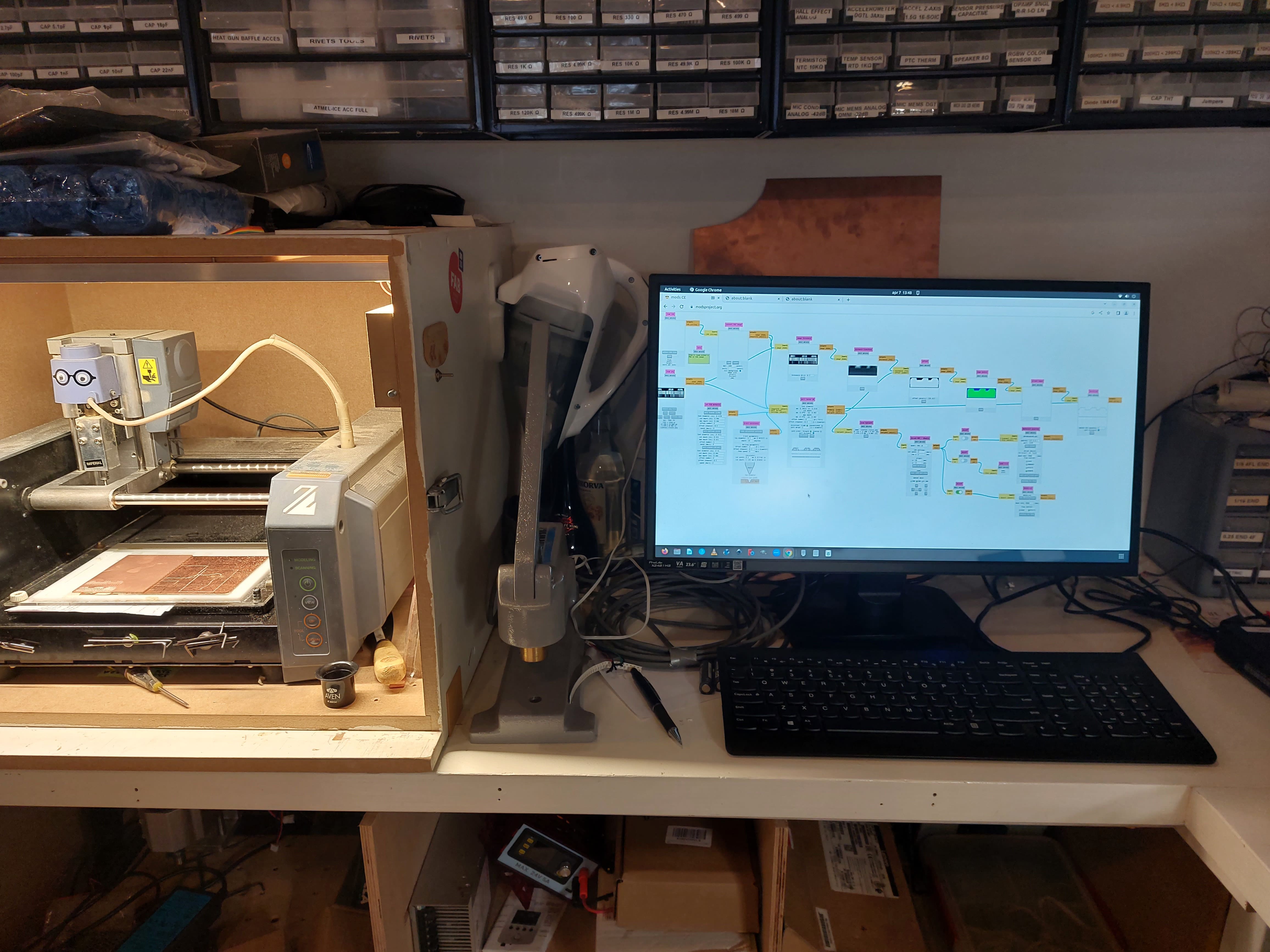
photo of modela MDX 20 station
Making your own in our Fablab
To design a circuit, we use kiCAD software. To learn how to do so before using the Modela MDX 20, refer to my kiCAD page
KEEP IN MIND!
: in comparison to our Shopbot milling machine, this machine has a small bed for milling
: the milling bits are fragile, use them with care
: avoid touching the copper plate or sacrificial layer with your fingers too much
: because we are working with very small measurements, even an ever so slight unevenness within any of the surfaces can influence the final product
: Roland MDX/ iModela module of mods (the software) operates the x- and y-axis, the z-axis is adjusted from the machine itself
ITS STRUCTURE
- The bed of the modela has 4 layers copper plate in which a circuit will be drilled
- sacrificial layer onto which the copper plate goes
- an acrylic plate with a pocket for the sacrificial layer
- another acrylic bed where the acrylic pocket is attached to
MILLING BITS
- 0,8mm to make edge cuts
- 0,4 mm to make interior cuts
MILLING BIT FLUTES
two types we use:
1 flute
- STANDARD: cuts faster because more material is eaten away at a time
2 flutes
- more precise but also takes more time to complete job
PREPARATION AT MACHINE STATION
1.
Measure the thickness at different areas of the copper plate you will be drilling onto, and write these down for later.
2.
If a new copper plate is needed, remove the previous plate carefully. Clean the sacrificial layer clear of tape residue from a previous use
- firstly use the knife at the station to loosen the tape strips. Take care not to scratch the sacrificial layer when doing so.
- with sticker remover, get rid of the remaining excess residue. Let this evaporate for a couple minutes before continuing.
3.
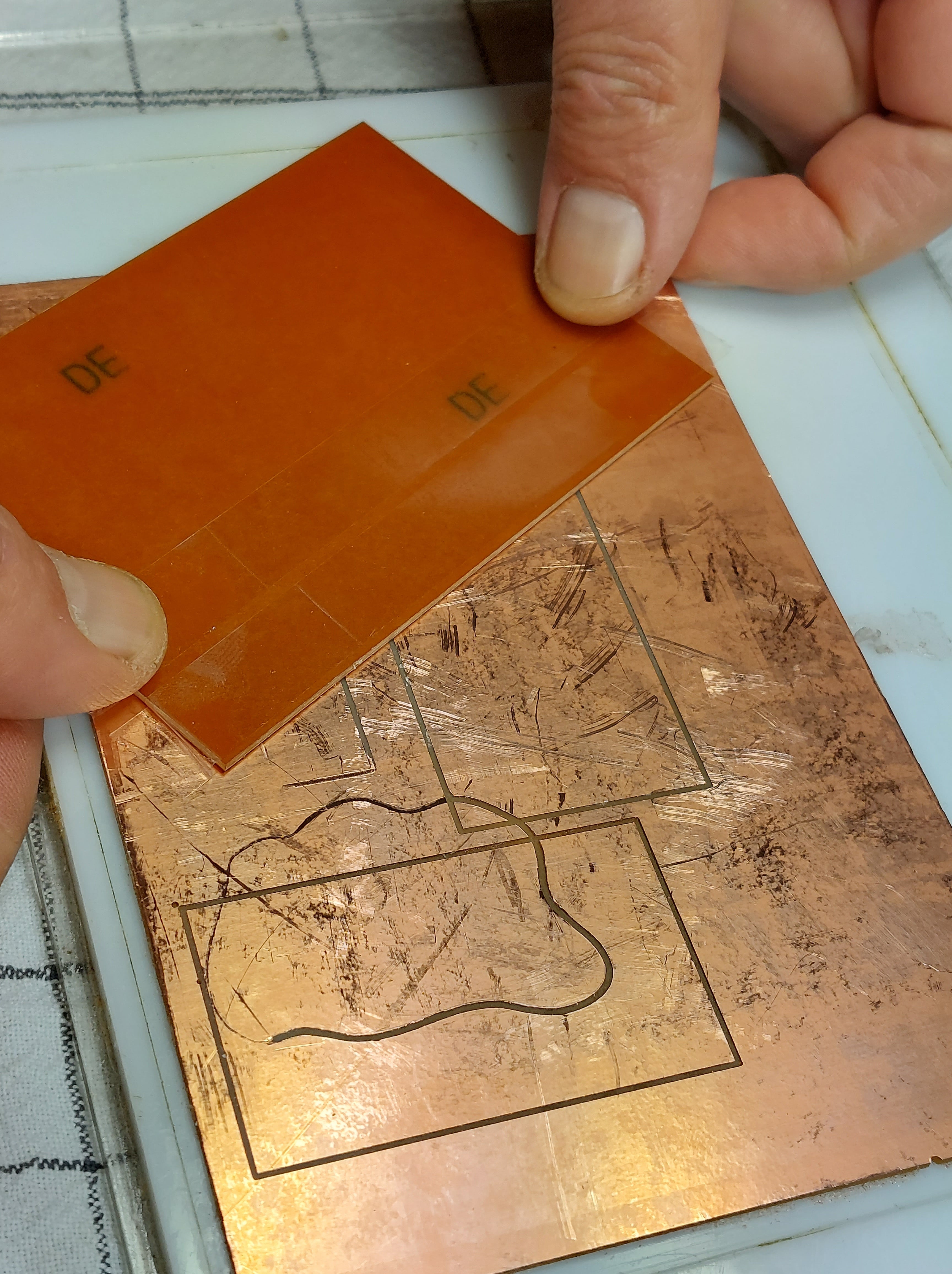
Fully cover the area on the sacrificial layer that your copper plate will lie on, with double-sided tape. Avoid overlapping the seperate pieces of tape.
4.
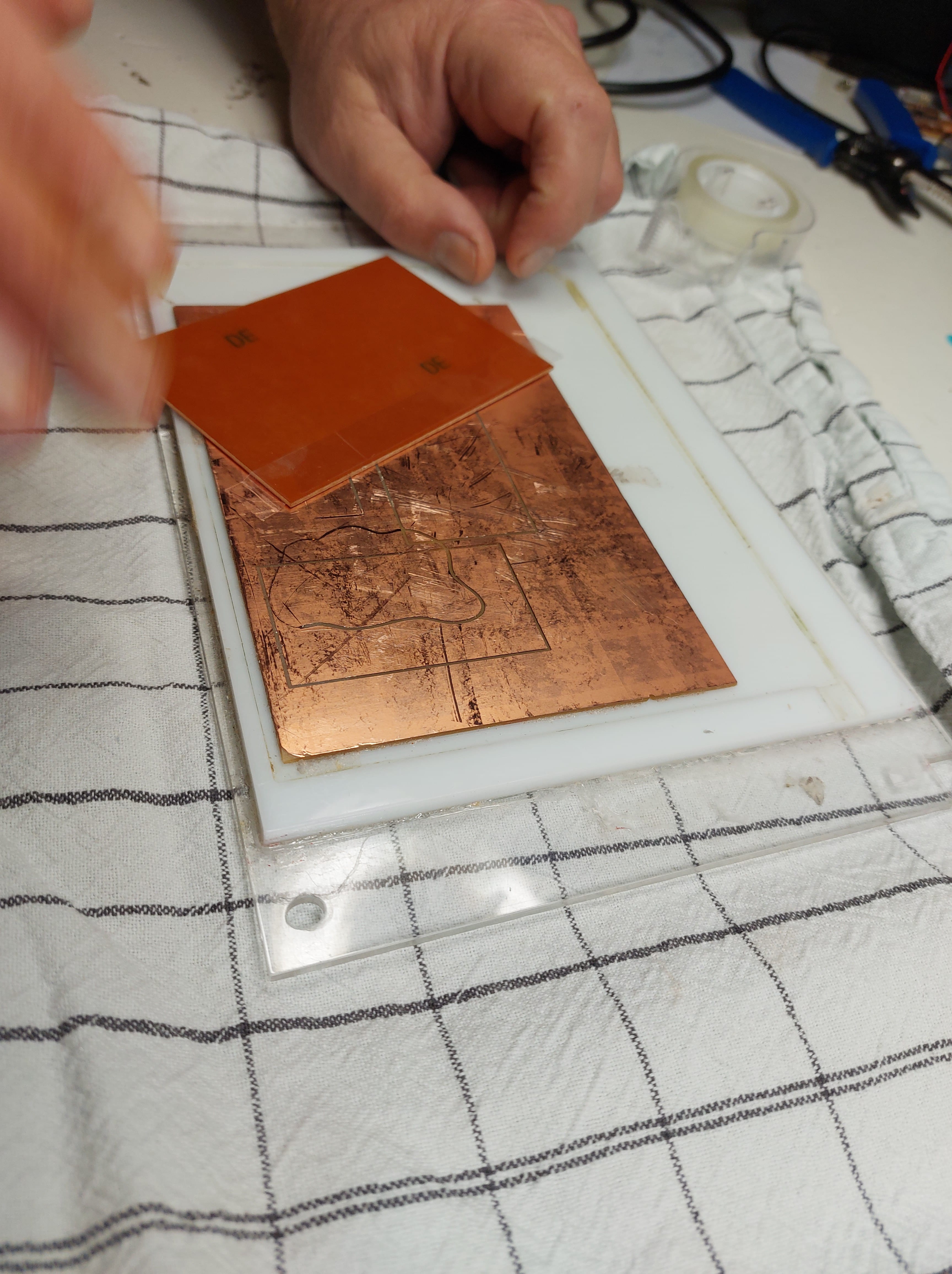
Grab a clean kitchen towel. Using a paper towel, firmly place the copper plate on the taped out area on the sacrificial layer.
5.
Lie the plates copper side down on the towel and put pressure from the acrylic bottom to seal the tape. The towel is to avoid damage to the copper plate.
6.
Flip the plates and screw the acrylic plate back onto the bed of the Modela.
7.
The milling bits are held in the bit holder. On the head of this bit holder, there are two screws. To loosen and replace the milling bit, unscrew (using the screw driver at the station) where Henk has made a black pen mark. You can’t release it and let it drop, because they are very fragile and will break. Take it out in a controlled way.
8.
Put the new milling bit all the way up into the bit holder (as far as it can go)
HOW TO USE FOR INTERIOR CUTS: STEP BY STEP
#1 Software: Mods
1a.
Open up chrome on the computer next to the Modela. We use this and not another browser, because it runs javascript and allows the reading of information on a USB.
1b.
Go to modsproject.org
#2 Machine: Modela
2a.
Press the ON/OFF button to start the machine.
2b.
It will go to home, if it is in view mode (goes all the way to the back) press the VIEW button to get out of the mode.
#3 Software: Mods
3a.
As shown in the images, open: - programs - open programs - MDX mill PCB (our machine)
3b.
In the node Websocket serial, close the ‘serialserver.js’ socket and port.
3c.
In the node Websocket pyserial, close the ‘serialserver.py’ socket and port.
3d.
Go back to the node Websocket serial, and open the ‘serialserver.js’ socket and port.
3e.
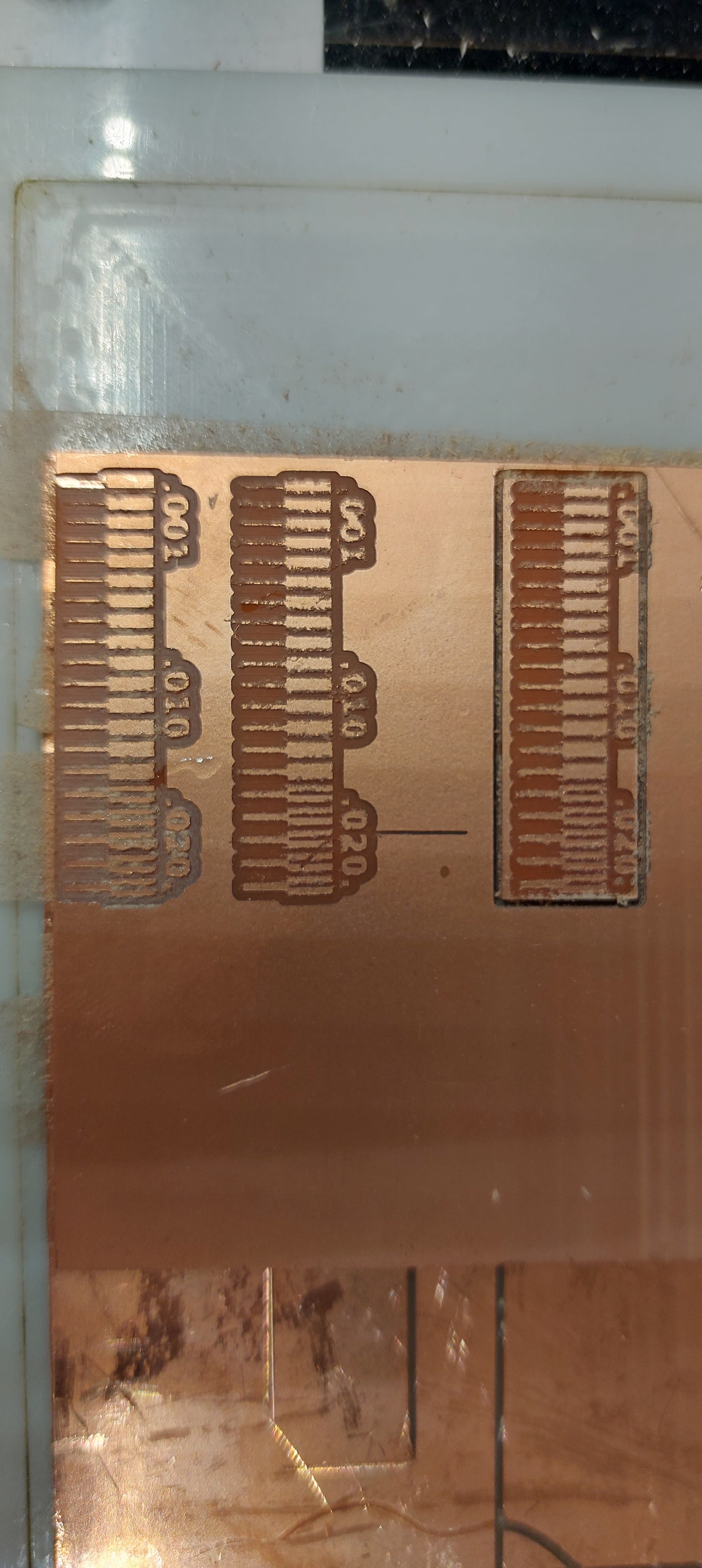
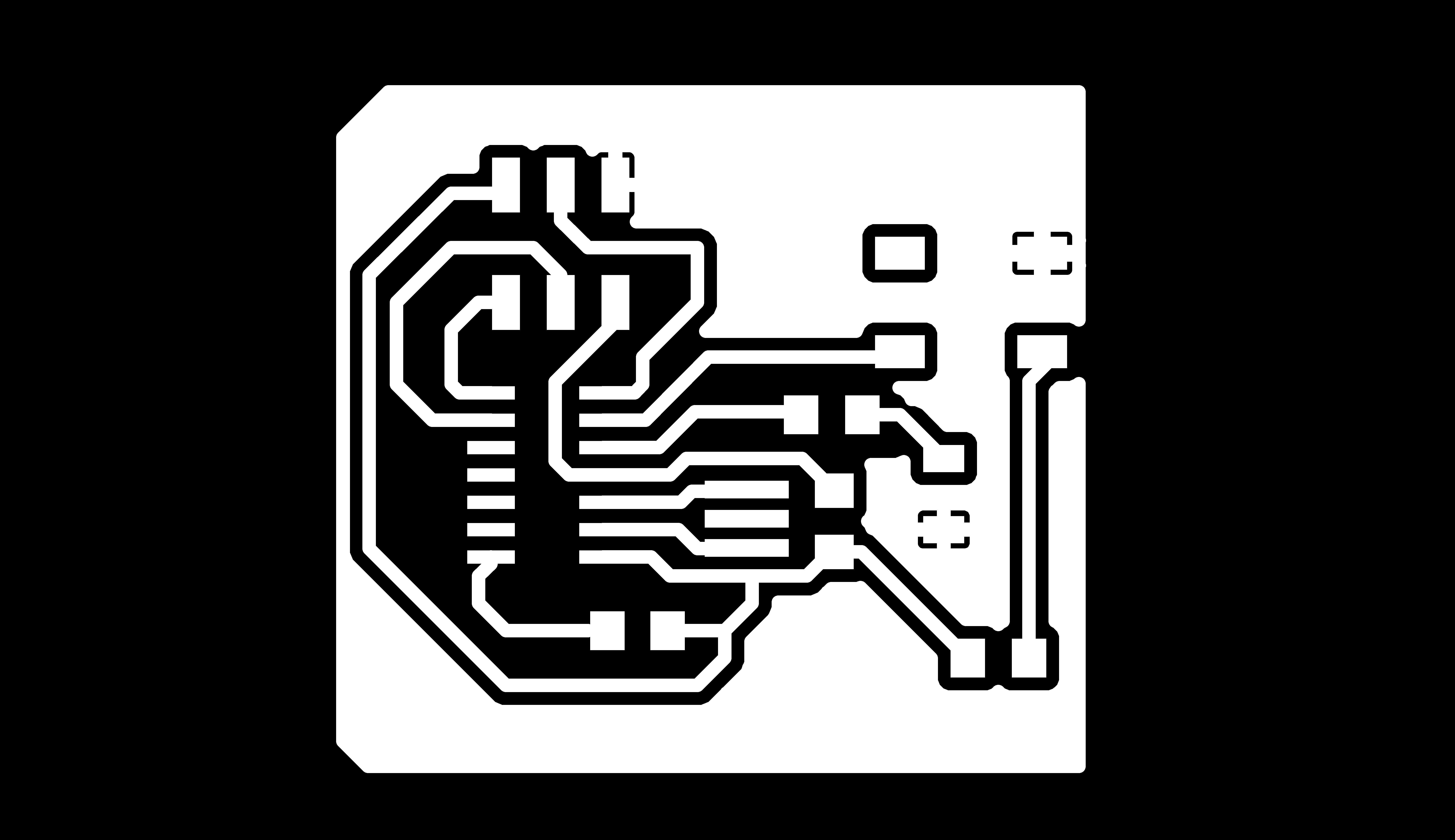
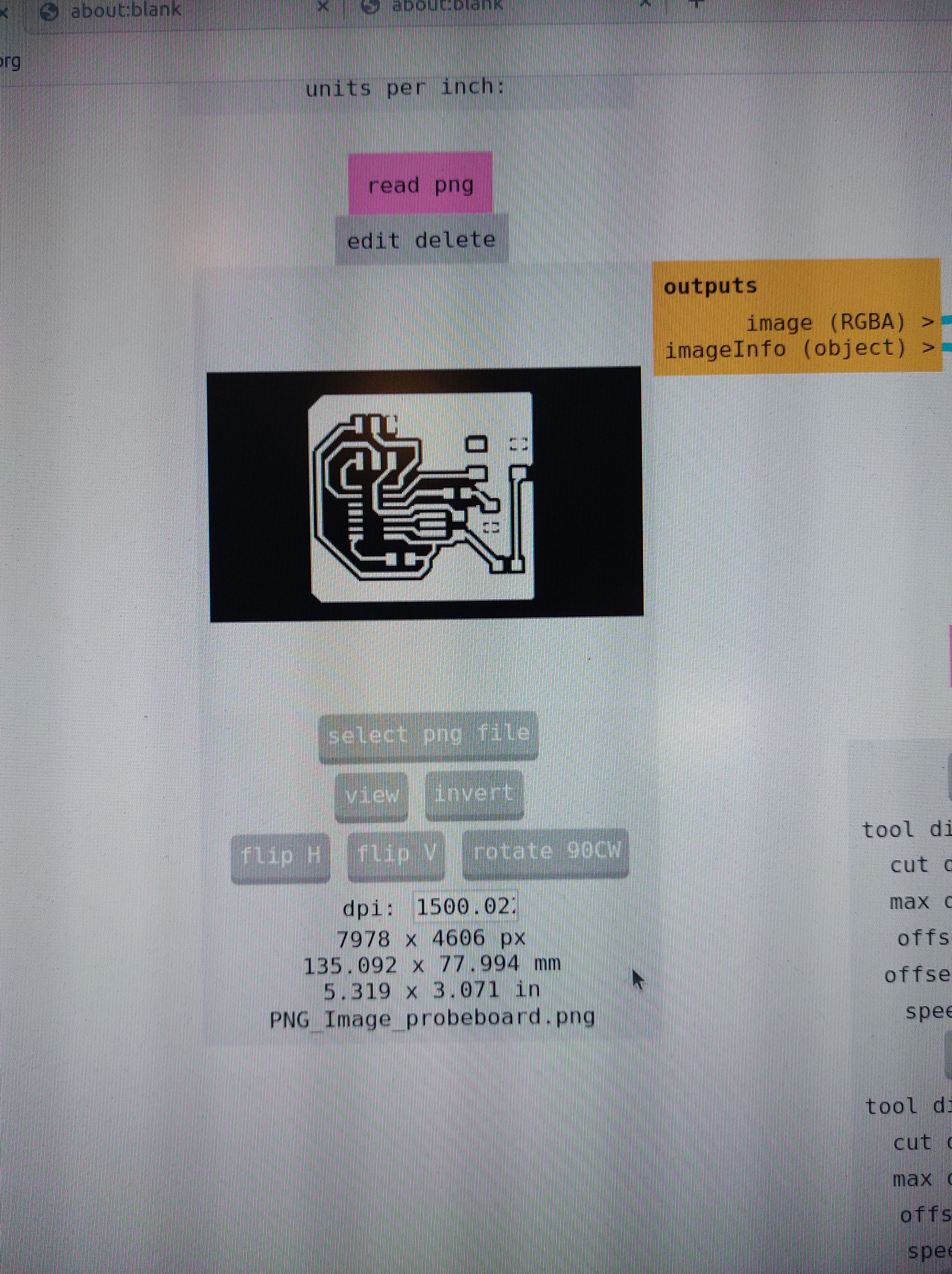
Within the nodes on the left ‘open png’ and ‘open svg’ you may open your file. - the white segments are what you want to keep, black is what will be drilled. - check the size of the design and make sure it is what you intend. - check the DPI value; if it is below 1000 change it to so.

3f.
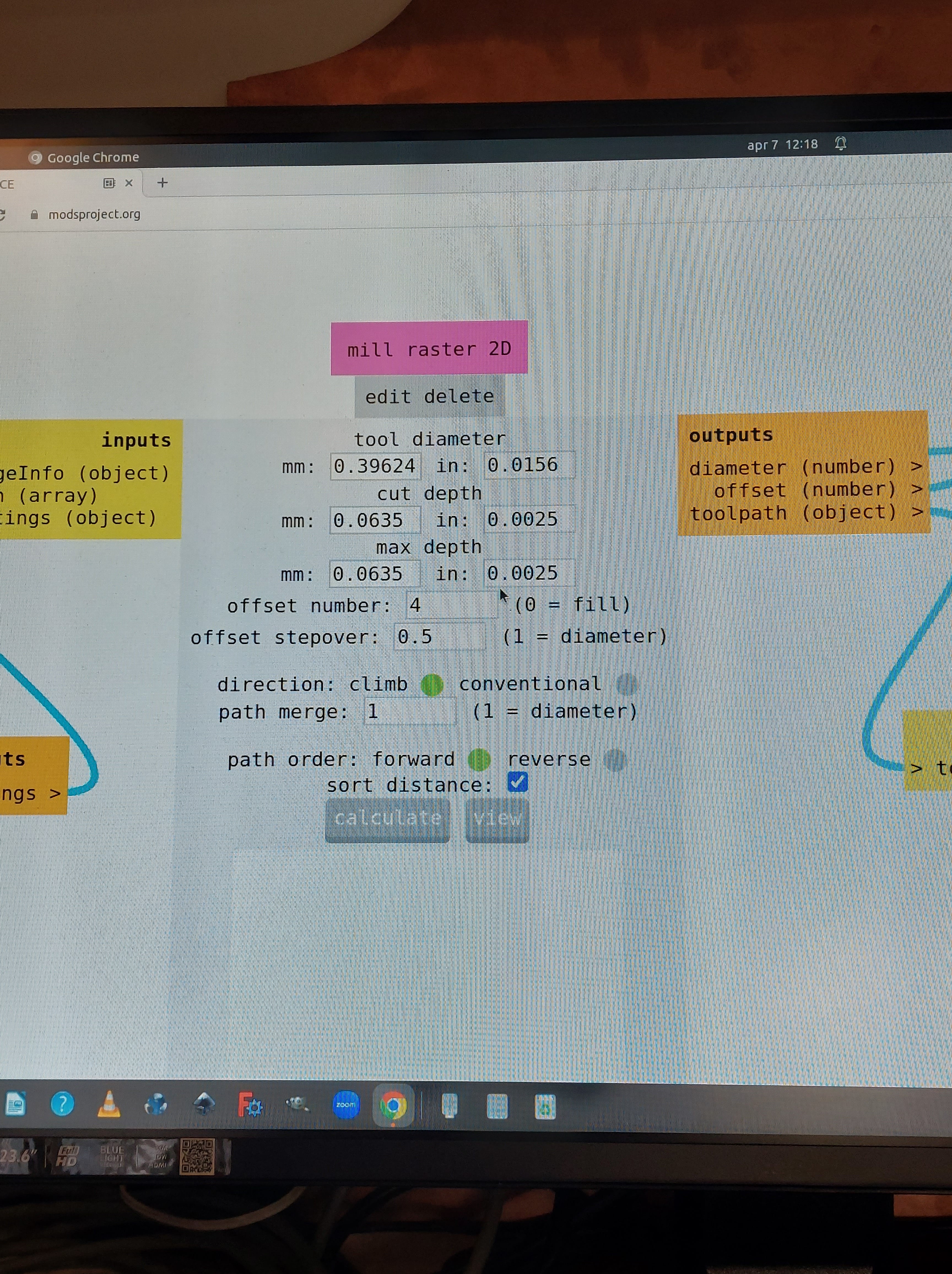
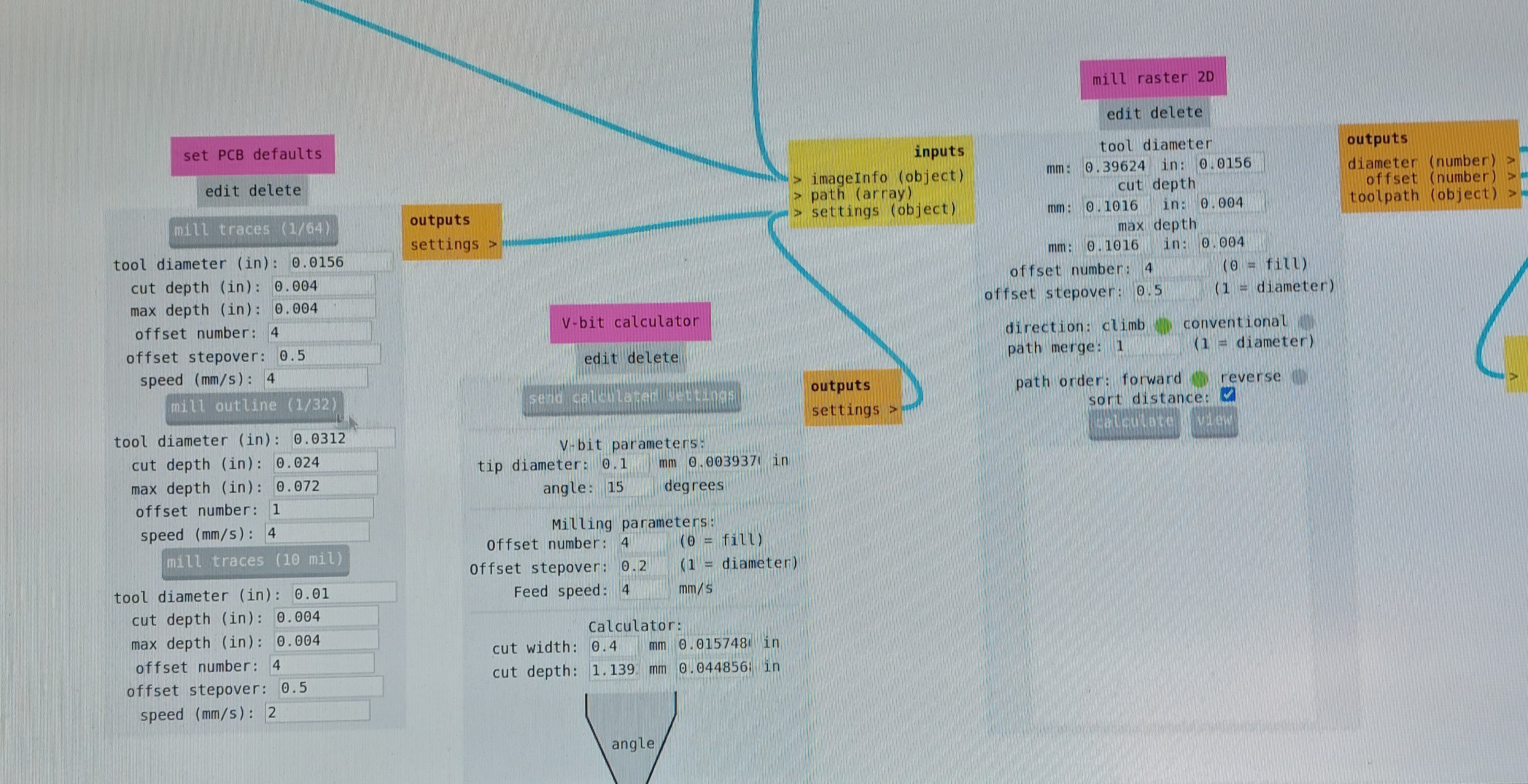
In the node Mill Raster 2D, look at :
-
the ‘offset number’: This is the maximum amount of traces from the lines you want to keep. 4 is a good value to work with, as it allows enough space to solder easily. 0 would mill off everything except for the lines.
-
the ‘offset stepover’: half of the tool diameter so you are sure it takes off everything.
-
view the toolpath to make sure all looks correct. A new tab will be opened for this.
-
‘cutting depth’ is 0.004
-
keep the direction ‘climb’
-
‘path merge’ should be the diameter of the tool
-
keep the ‘path order’ set as ‘forward’
You can now click ‘CALCULATE’
3g.
In the node image threshold, you can adjust the threshold if necessary. If you do so, you need to hit ‘CALCULATE’ again in the node Mill Raster 2D.
3h.
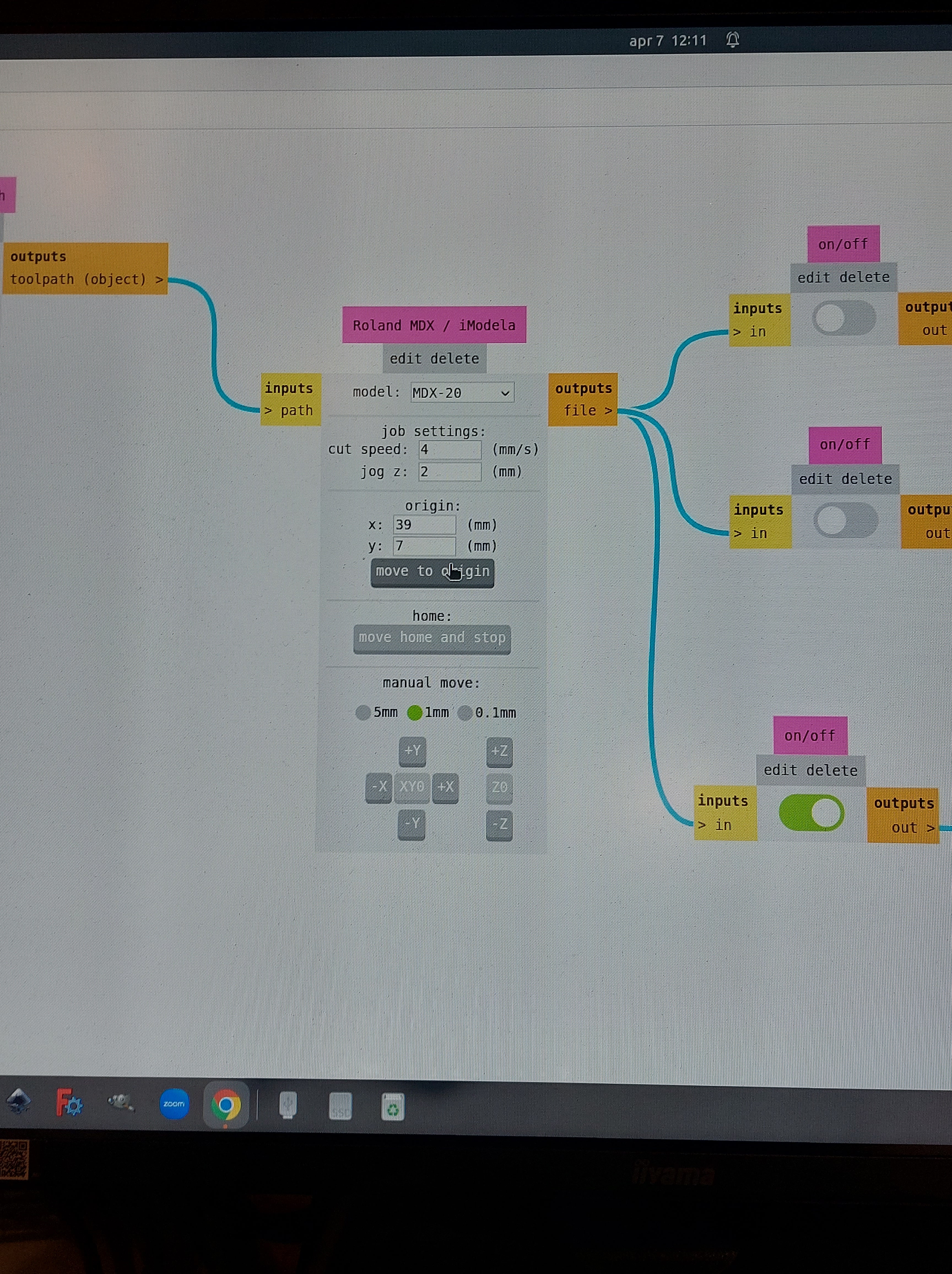
In the node Roland MDX / Modela, define the cutting speed. (4)
#4 Machine: Modela
4a.
Using the arrow keys on the machine interface, move the milling head to where you want the job to start on the x- and y- axis. Check that there is space for your design on your material and it doesnt exceed its edge.
4b.
Check what its coordinates are and remember them.
#5 Software: Mods
5a.
In the same node as we were in before (Roland MDX/Modela), define an origin point. Make note of this origin node. This is where your print will start.
#6 Machine: Modela
6a.
Defining the z-axis:
-
We moved the milling bit all the up in the preperation. Move all the way down with the machine using the up and down buttons on the machine and not is mods.
-
Move it up slightly. The bit is floating above the material.
-
Lower the bit with the use of two fingers, until it touches the material you want to drill on. Wiggle it in case there is dust residue and then secure it in the machine.
-
Write down the origin or take a picture of it.
#7 Machine: Modela
7a.
In the Websocket pyserial node, hit SEND FILE. This will have the machine start drilling right away.
7b.
Once the job is done, vaccuum the material on the bed. You are now ready to edge cut.
HOW TO USE FOR EDGE CUTS: STEP BY STEP
Assuming you left everything on, continue with the following steps:
- Within the nodes on the left ‘open png’ and ‘open svg’ you may open your file.
- check the size of the design and make sure it is what you intend.
- check the DPI value; if it is below 1000 change it to so.
- white segments are what you want to keep, black segments and lines are what will be drilled.