What is CNC?
A manufacturing method that automates the control, movement and precision of machine tools through the use of preprogrammed computer software, which is embedded inside the tools
Our CNC Milling machine : SHOPBOT
Softwares: Vcarve Pro, Shopbot 3

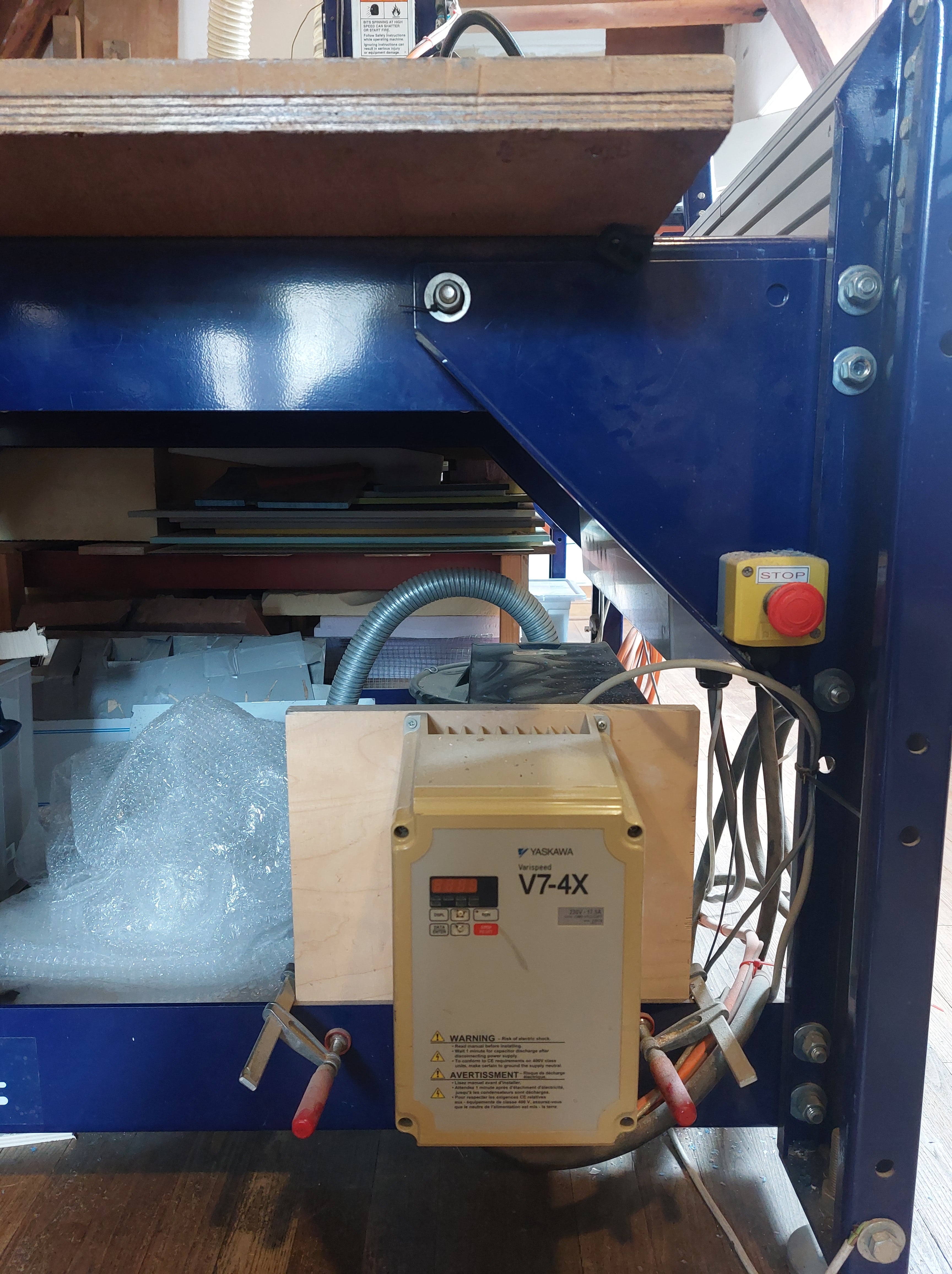 image of verispeed
Uses
- constructing large components
- making molds
- designing in 2+1/2 dimensions
Safety Highlights
-
milling bit rotates at 18000 rpm, so if anything creates high resistance like metal, it can be very dangerous. Always check the material you are milling into for foreign objects.
-
There is an emergency safety knob accessible in case anything does go wrong
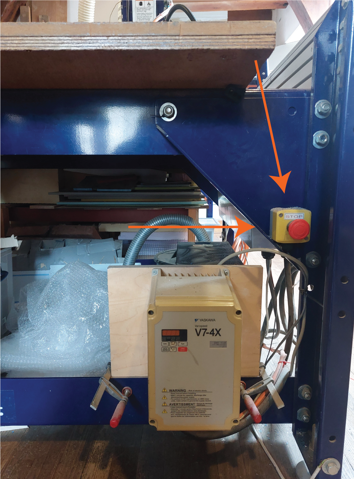 emergency shut down button
In Practice
General Cleaning around the machine
-
Check around all 3 axis of the machine, where the paths of movement is clear and free from obstructions.
-
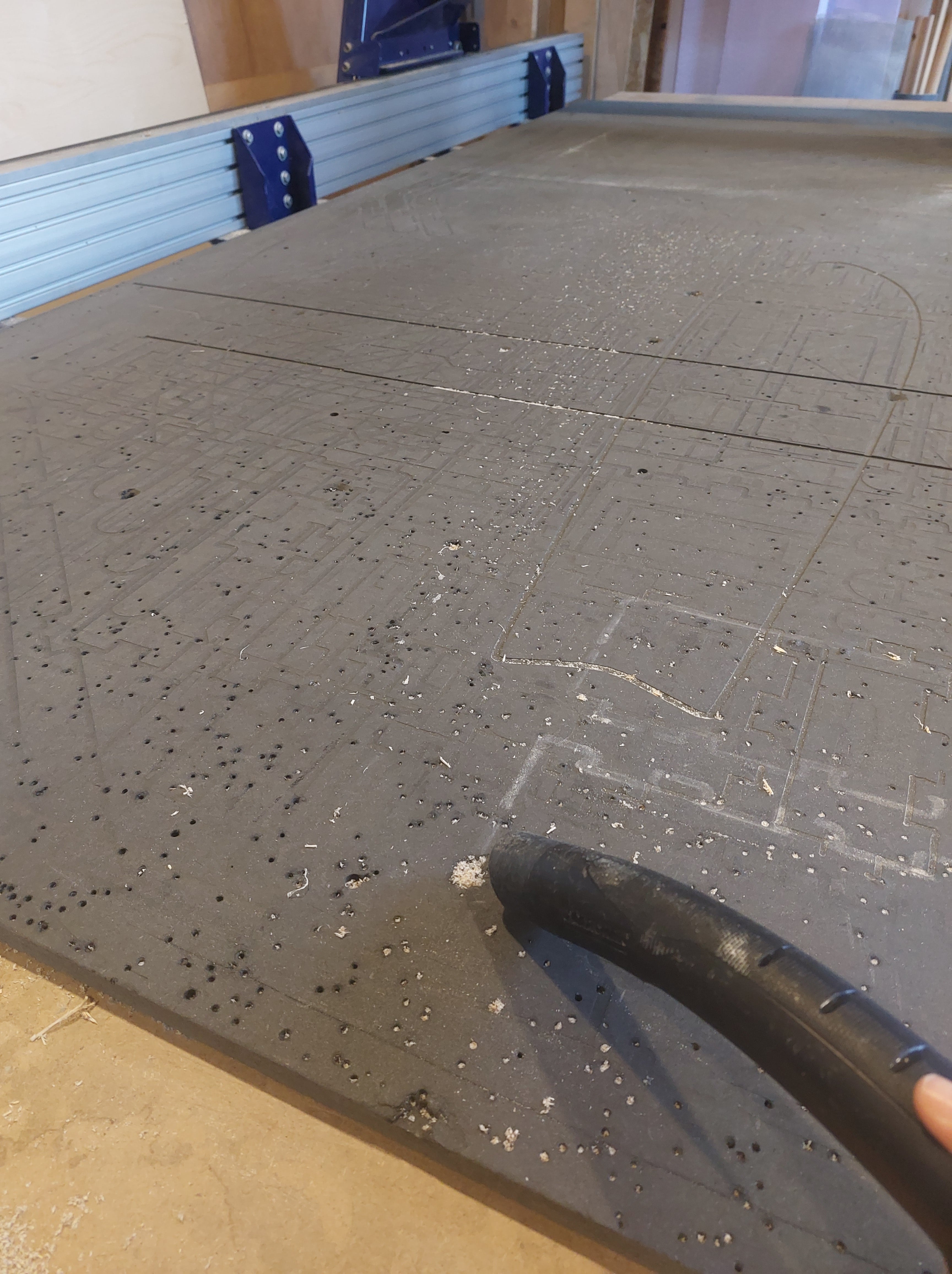
Clean the bed of the machine, including the sacrificial layer. You can use a vaccuum if necessary.
-
When screws are removed from the sacrificial layer, it could create extruding material. Check if there is any, and use sand paper to clear it.
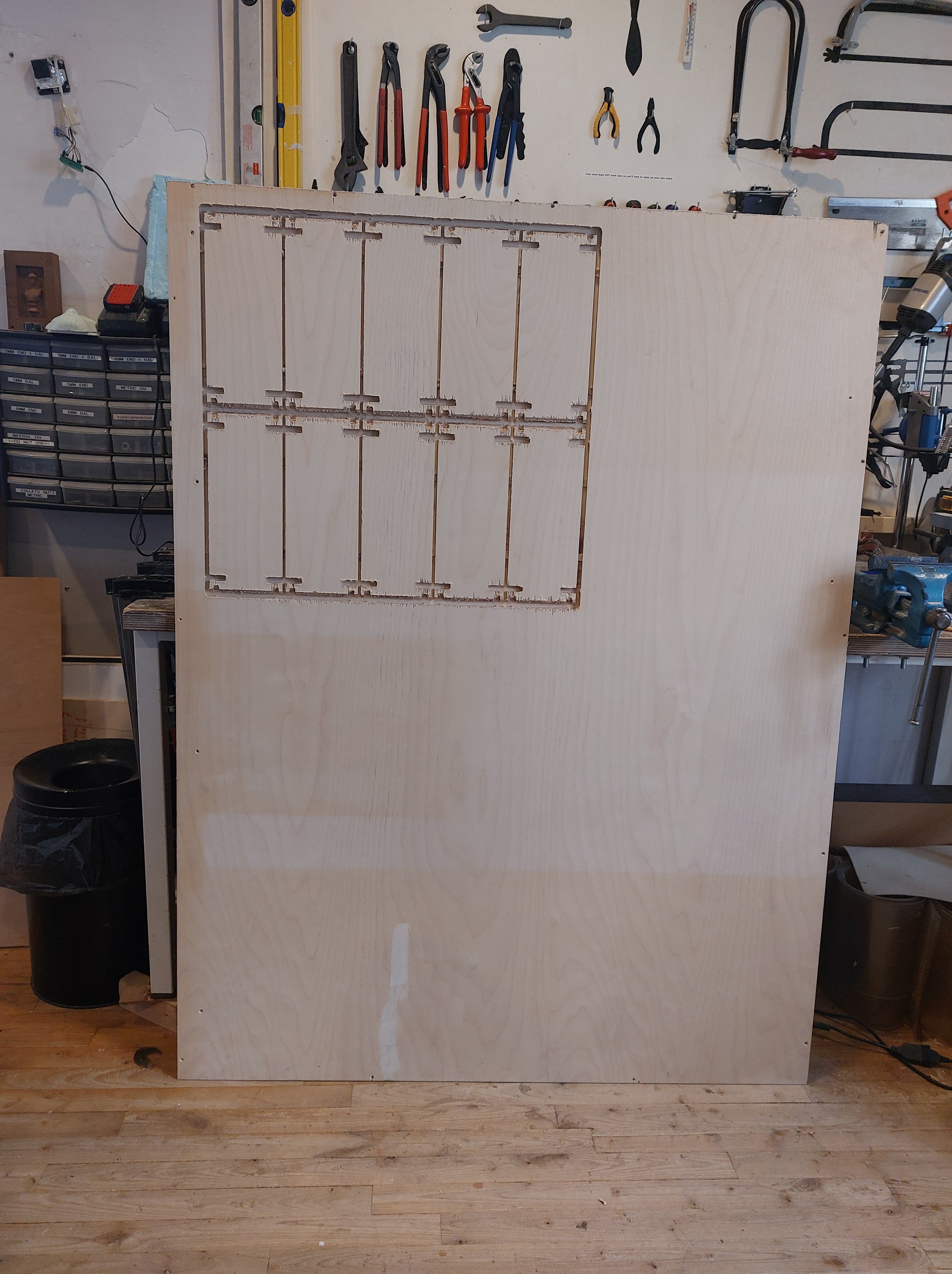
Identify material and place on sacrifical layer
- Having chosen your material beforehand, measure its thickness at several different points. Write it down. We will be using the largest value later on.

-
Measure the length and width of the sheet of material.
-
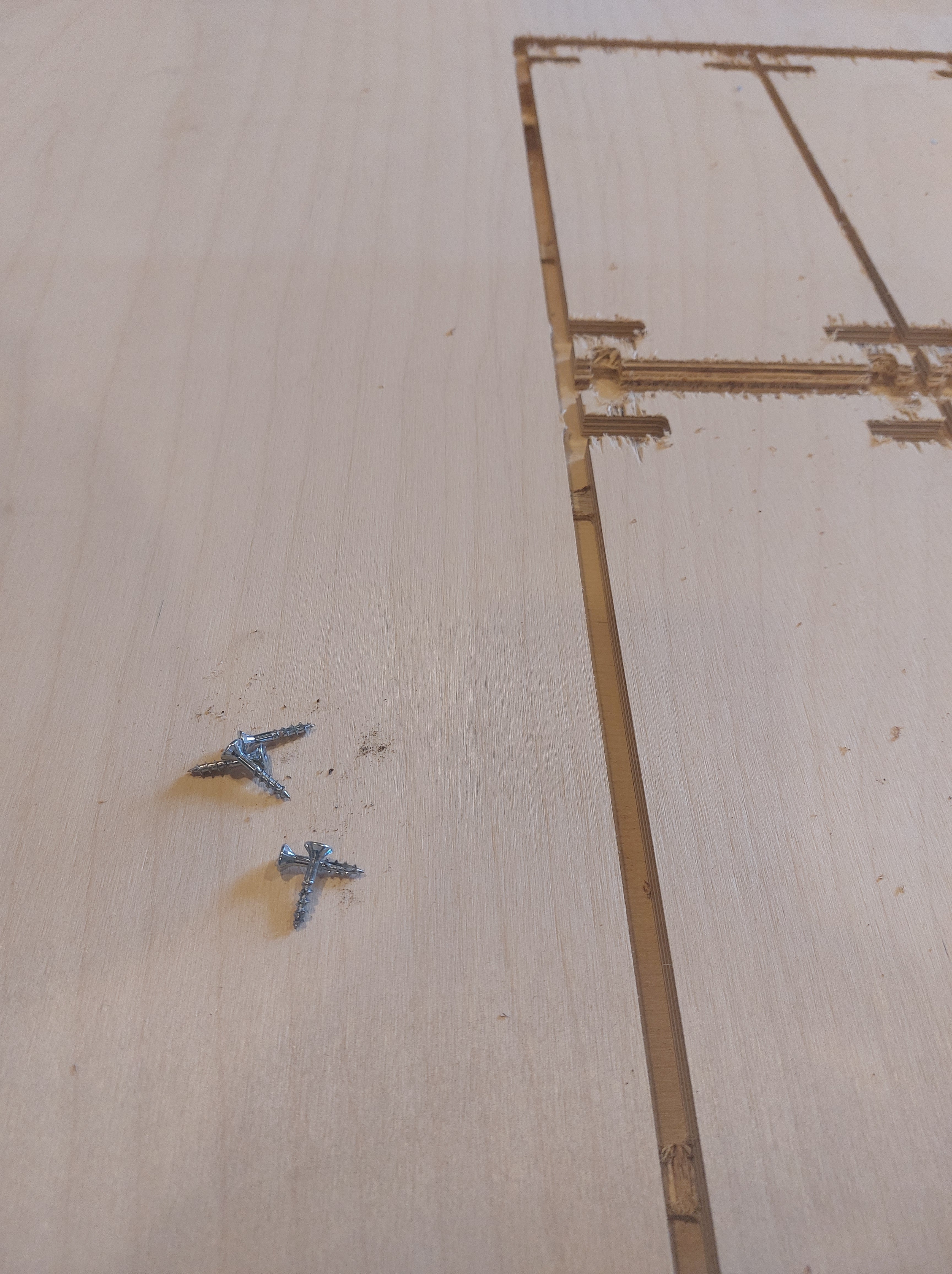
Check your material for foreign object such as screws. It is very important to remove these, especially objects made of metal.
 material placed
Turn on CNC milling machine
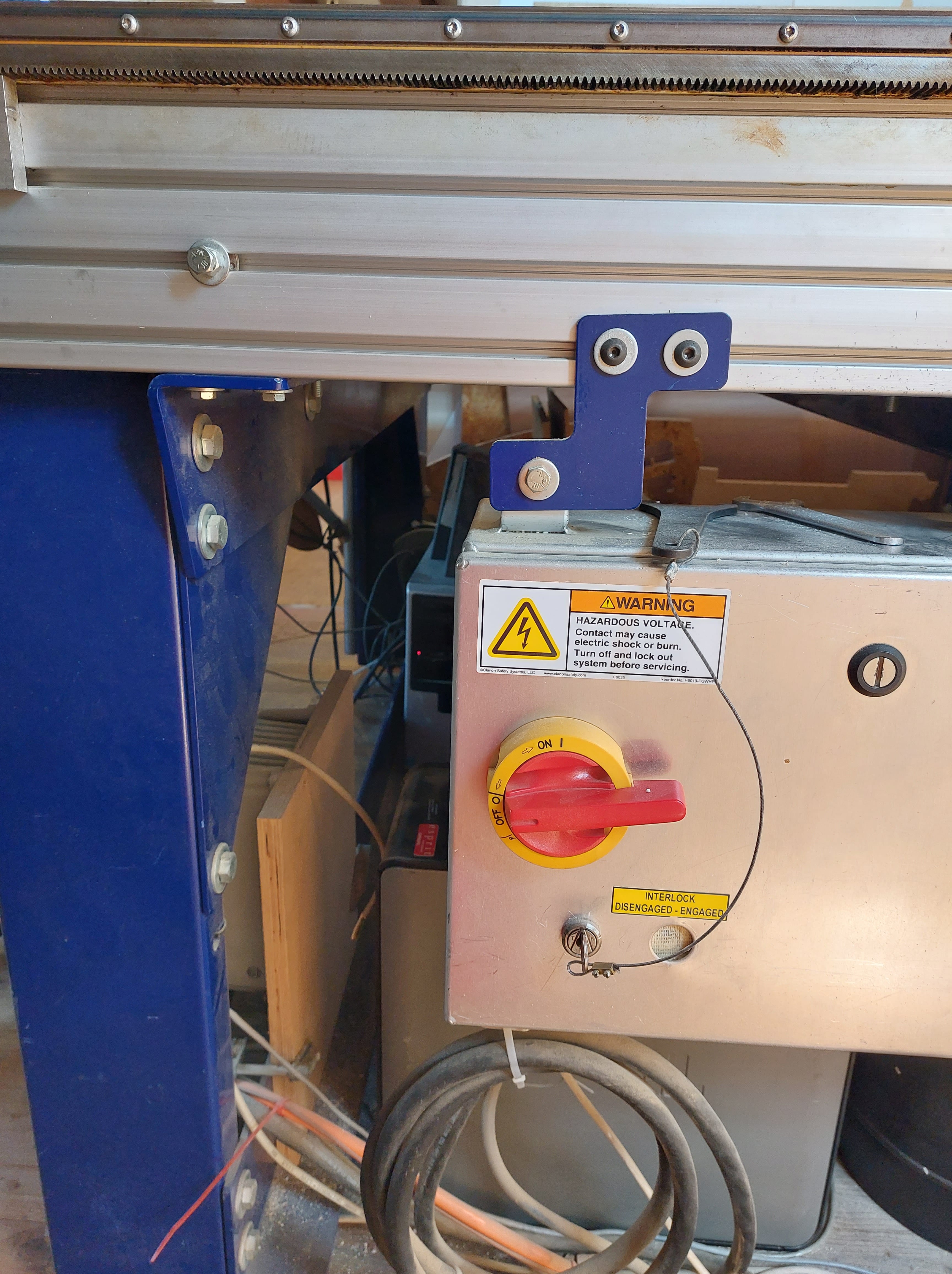
- Rotating the knob clockwise
Open software Shopbot 3
- Identify the COMMAND BOX
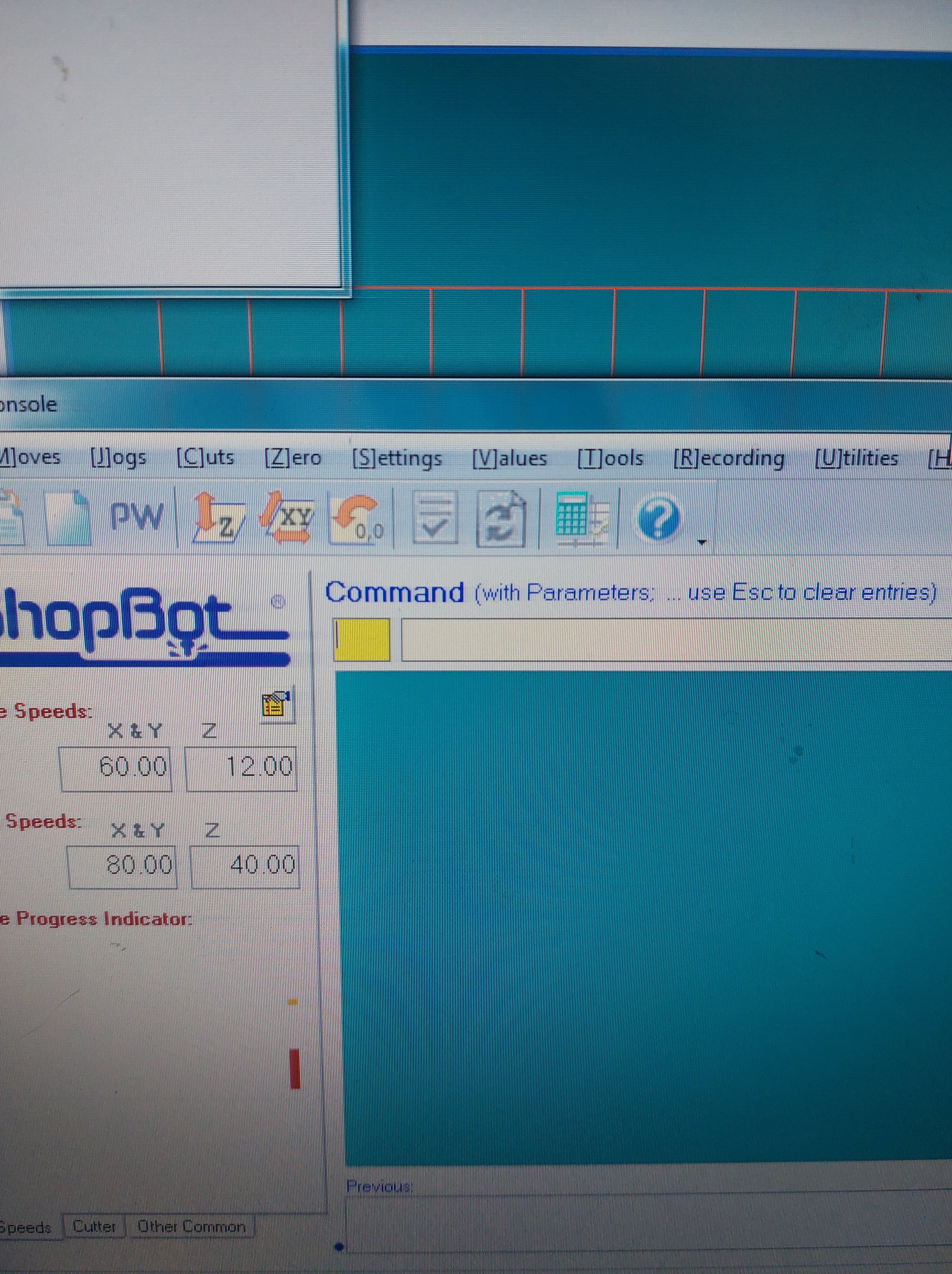 command box
-
By typing key ‘K’, you open the keypad. With this, you are able to control the milling head.
-
By using the arrow keys, bring the milling head towards you so that you can change the collet and milling bit.
good to know!
UP, DOWN, LEFT and RIGHT keys control the movement on the x and y axis
PAGE UP and PAGE DOWN keys control the movement on the z axis
CTRL and CONTROL KEYS on your keyboard allow for faster movement.
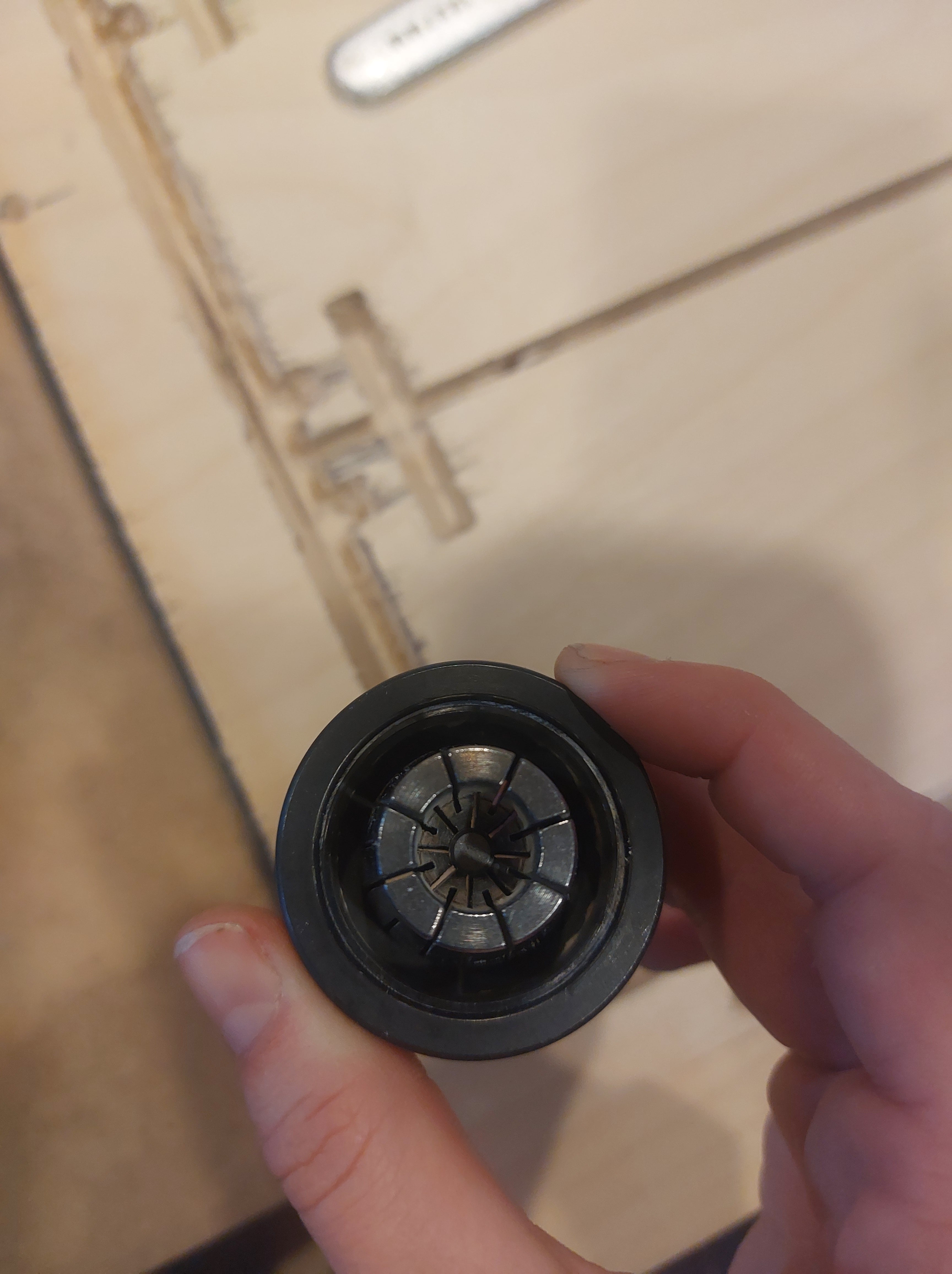
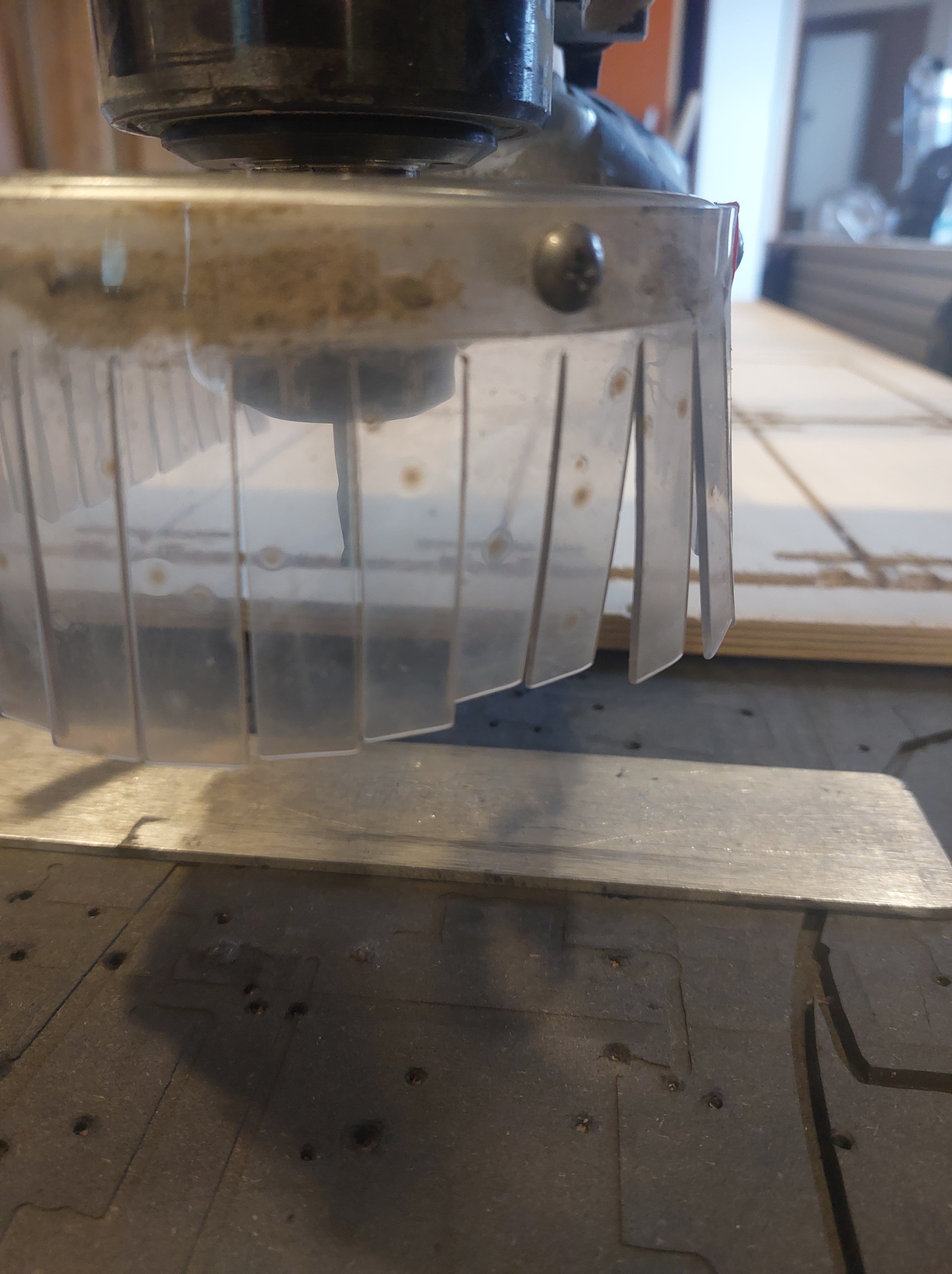
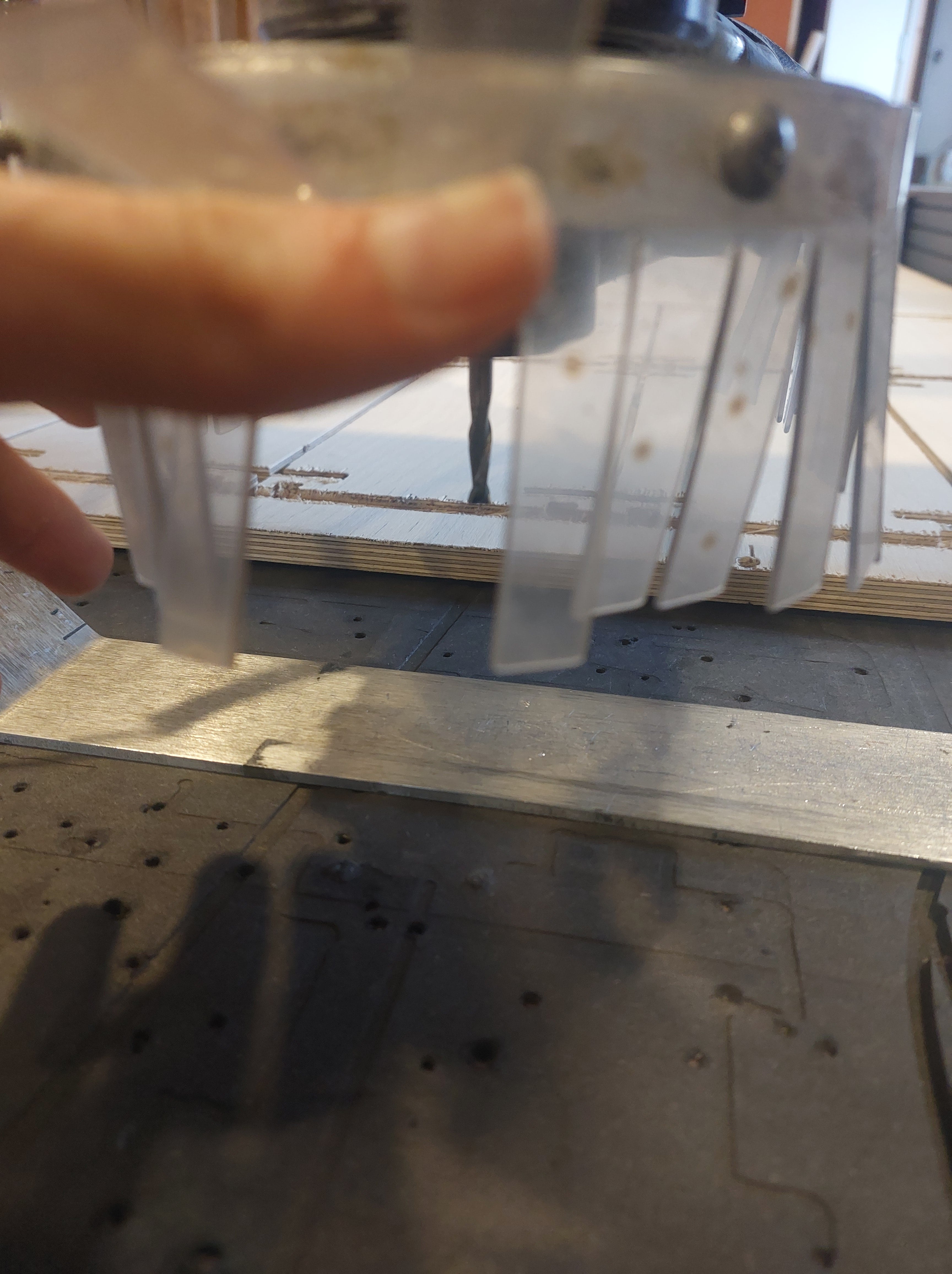
Change the collet
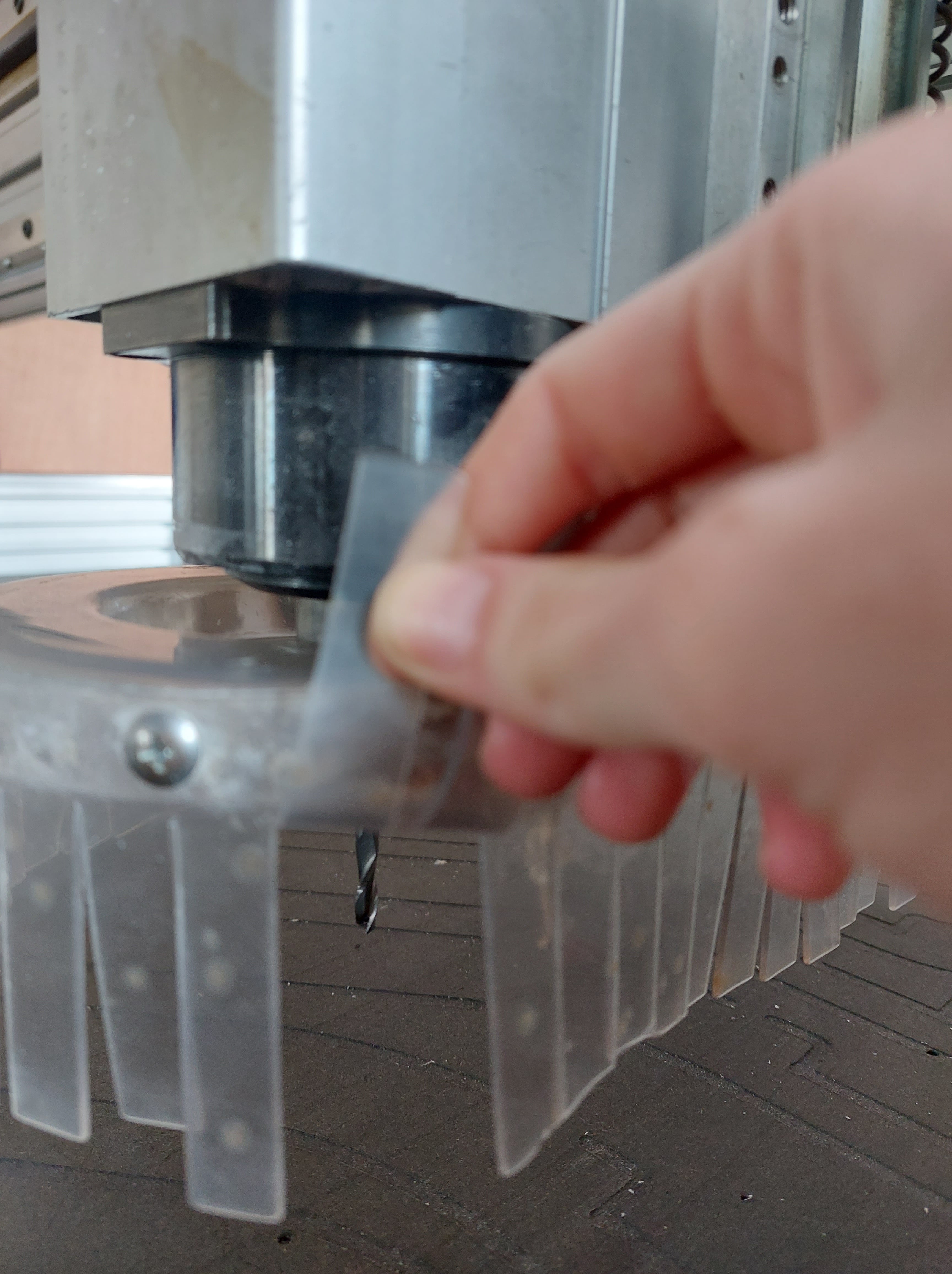
 skirt
skirt
(image of clamping nut, collet and milling bit)
- Bring the skirt down, by loosening the butterfly nut found as shown in the image below.
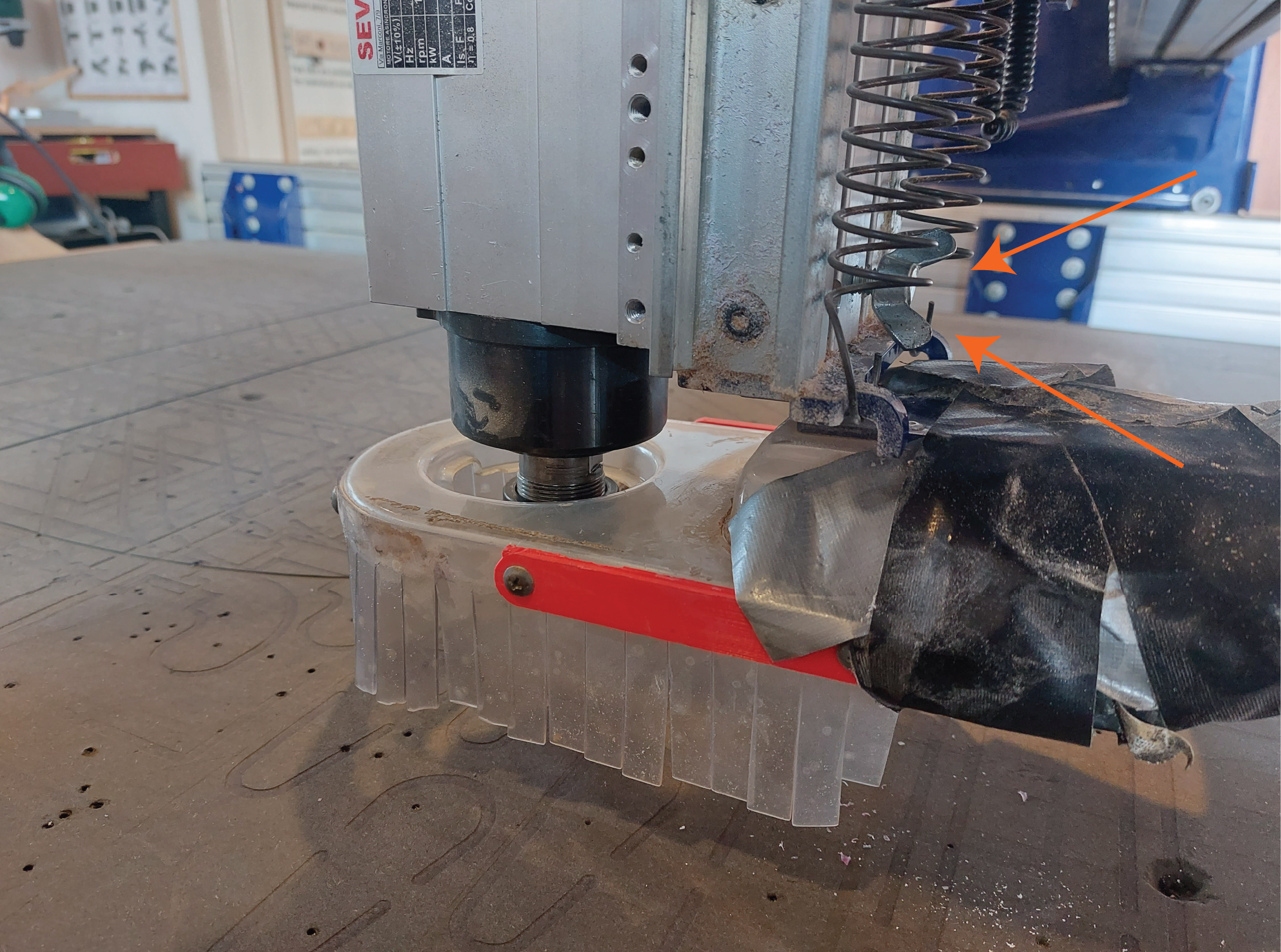 butterfly nut
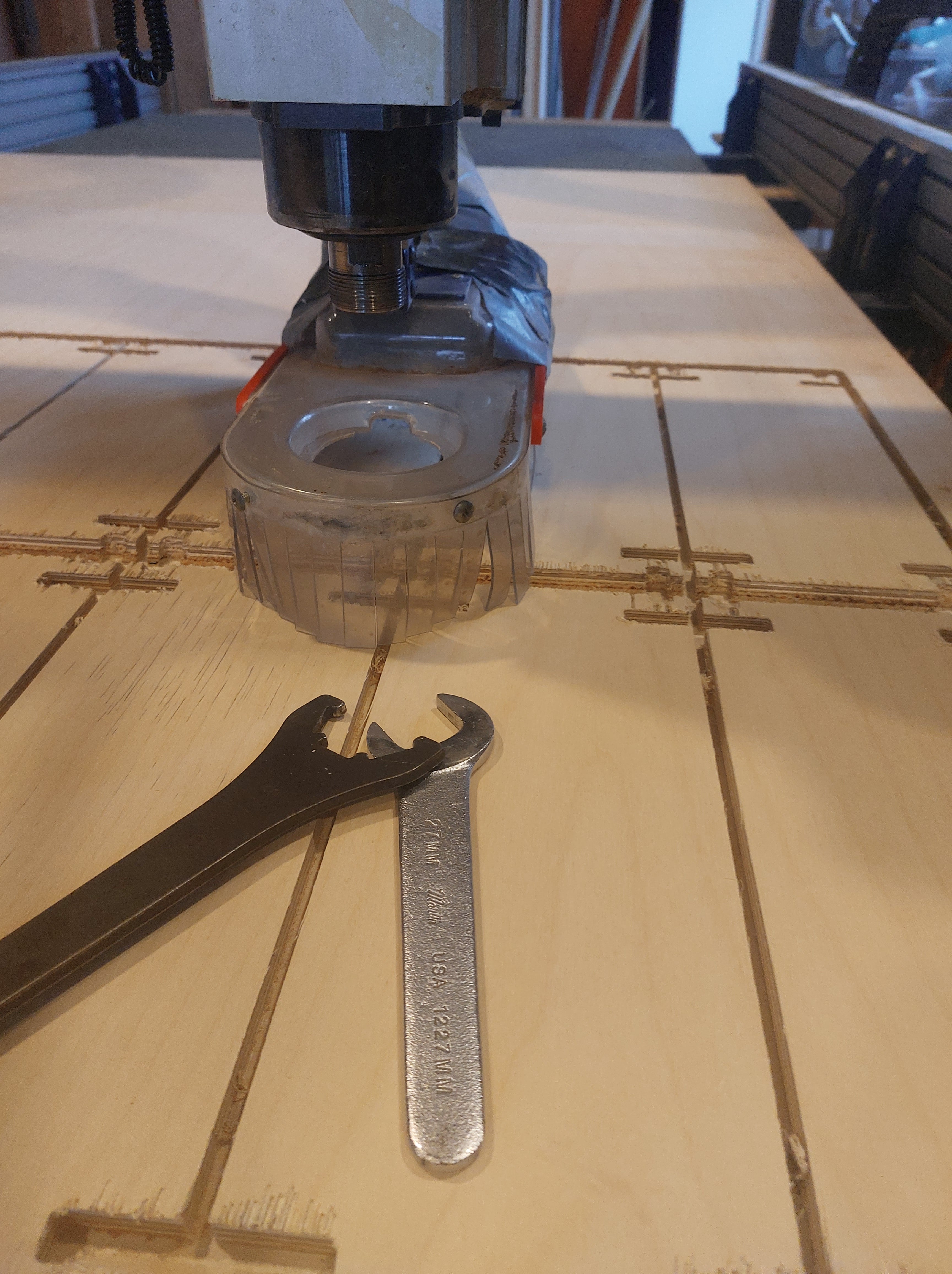
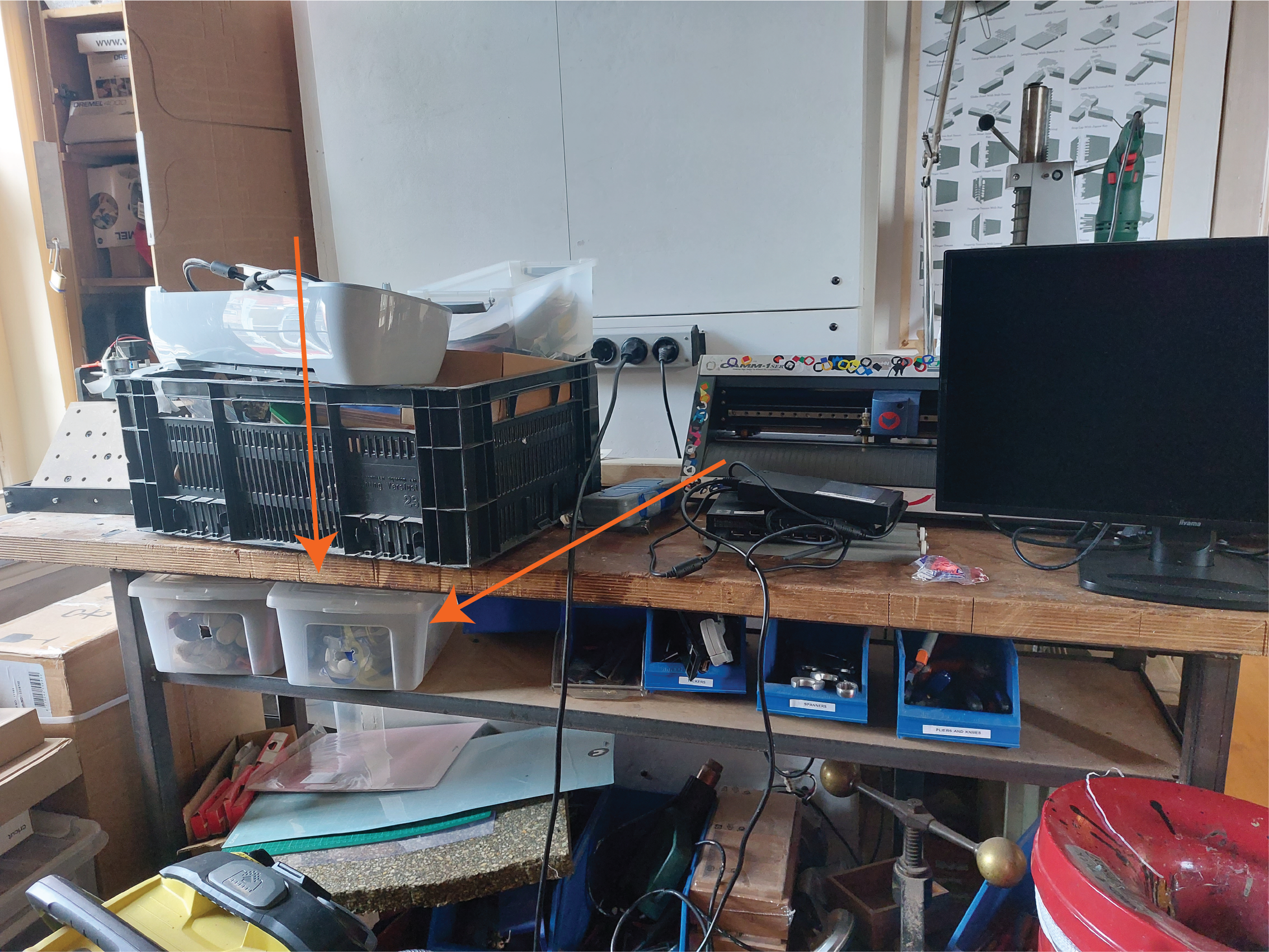
- Use the wrenches accessible at the station to loosen the clamping nut. These are attached to the key that allows powering the machine, so that these two tasks are never done at the same time.
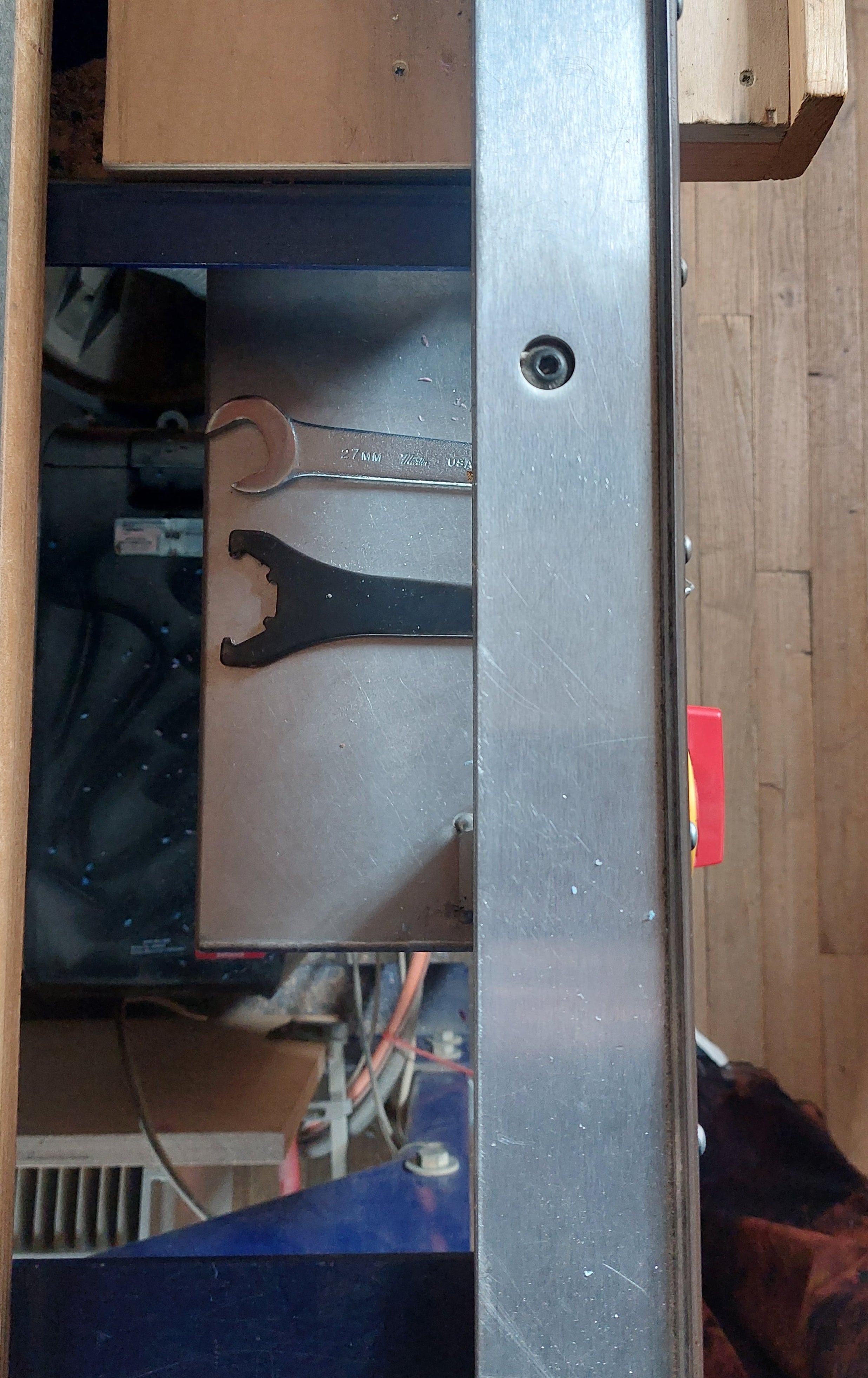 wrenches available
-
Once the clamping nut is loose, you are able to screw it out from the milling head alongside the collet and the milling bit.
-
Gather the milling bit that you require for your project, as well as the collet that matches it.
aspects to a milling bit to keep in mind:
shape of their tip
- There are two versions we use frequently here at Fablab
- The ‘base nose’ that is round and used for rounded details. This is useful for relief-like 2.5D work
- The ‘end mill’ that is flat and used for regular cutting and pocketing jobs
diameter
You decide the diameter of the milling bit depending on the level of detail you are working with.
number of flutes
Flutes refer to the sharp slots that corkscrew upwards along the length of the milling bit. The more flutes, the more precision possible.
Change the milling bit
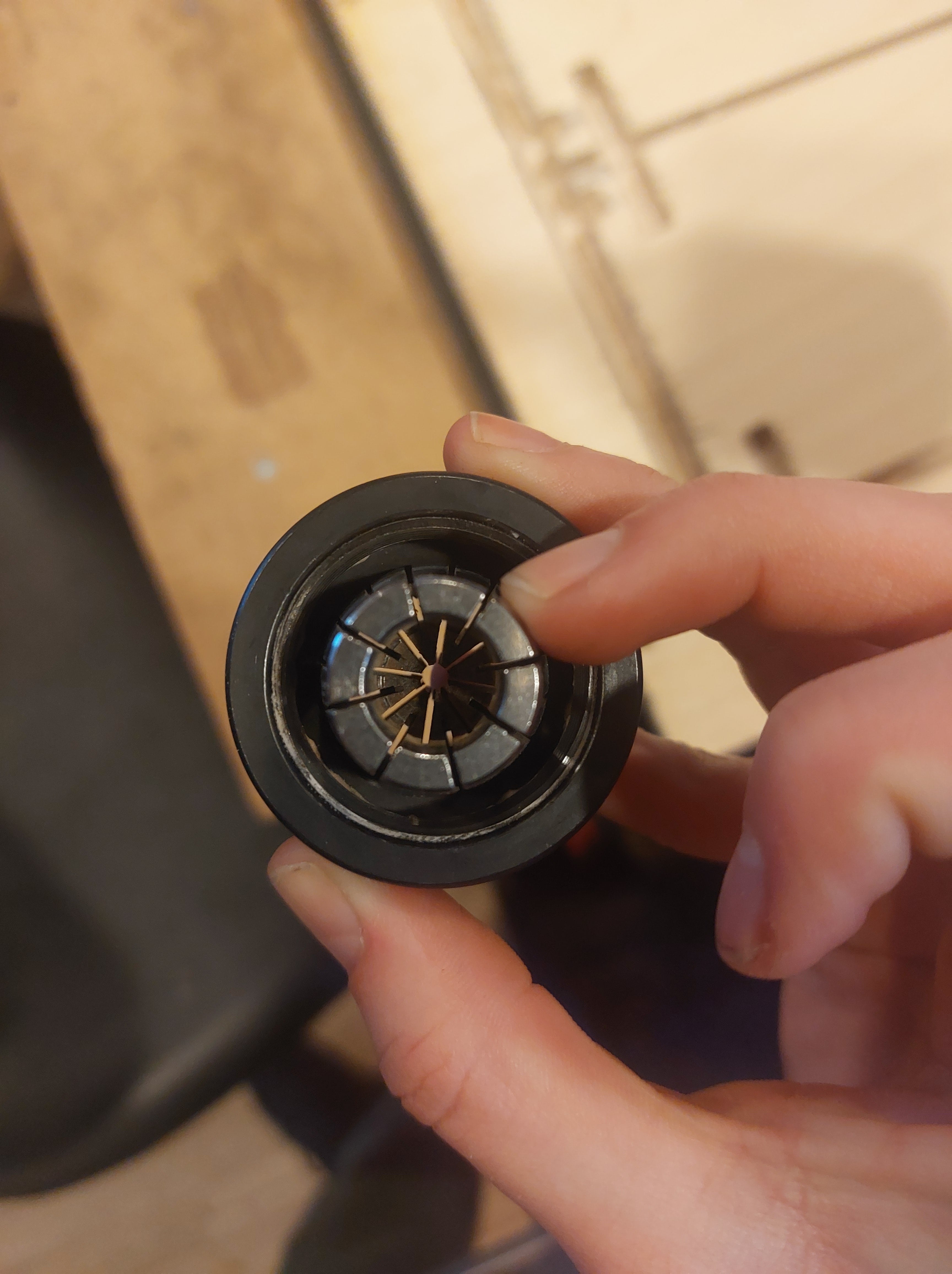
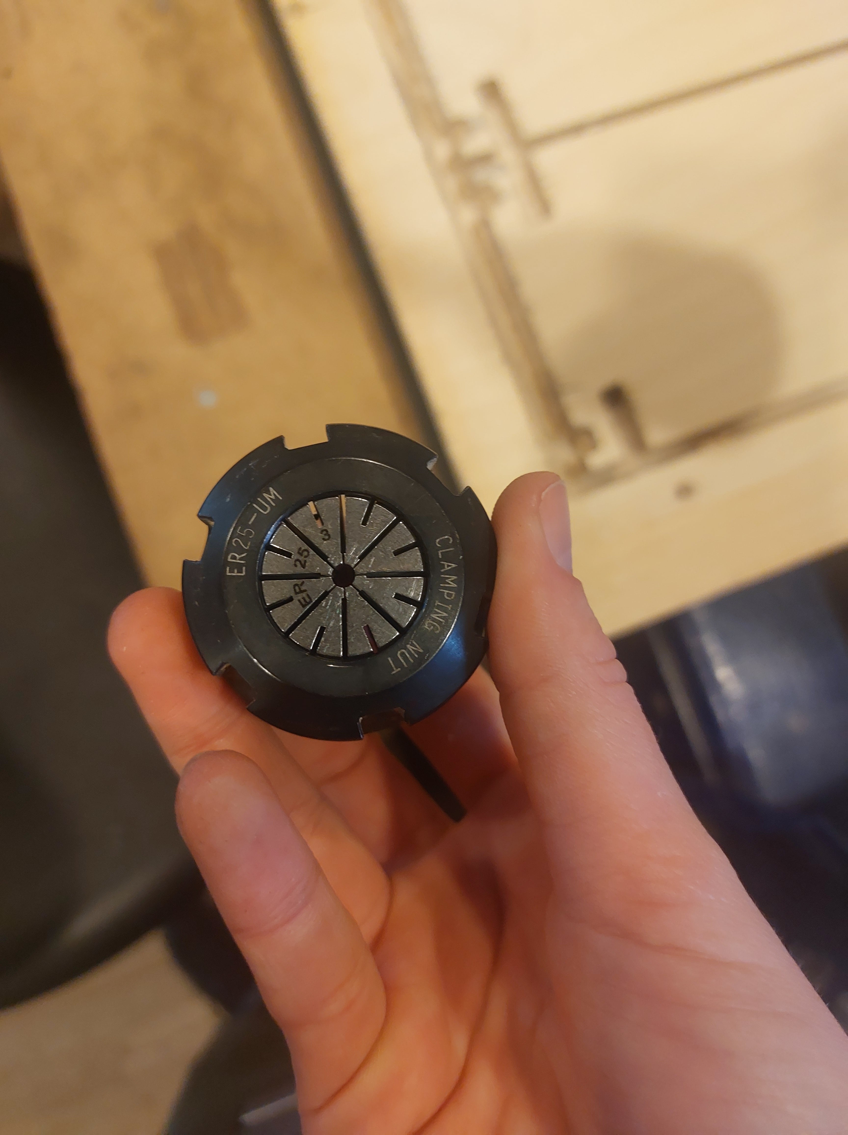 collet in clamping nut
- Place the collet in the clamping nut like shown above and push until you hear a click.
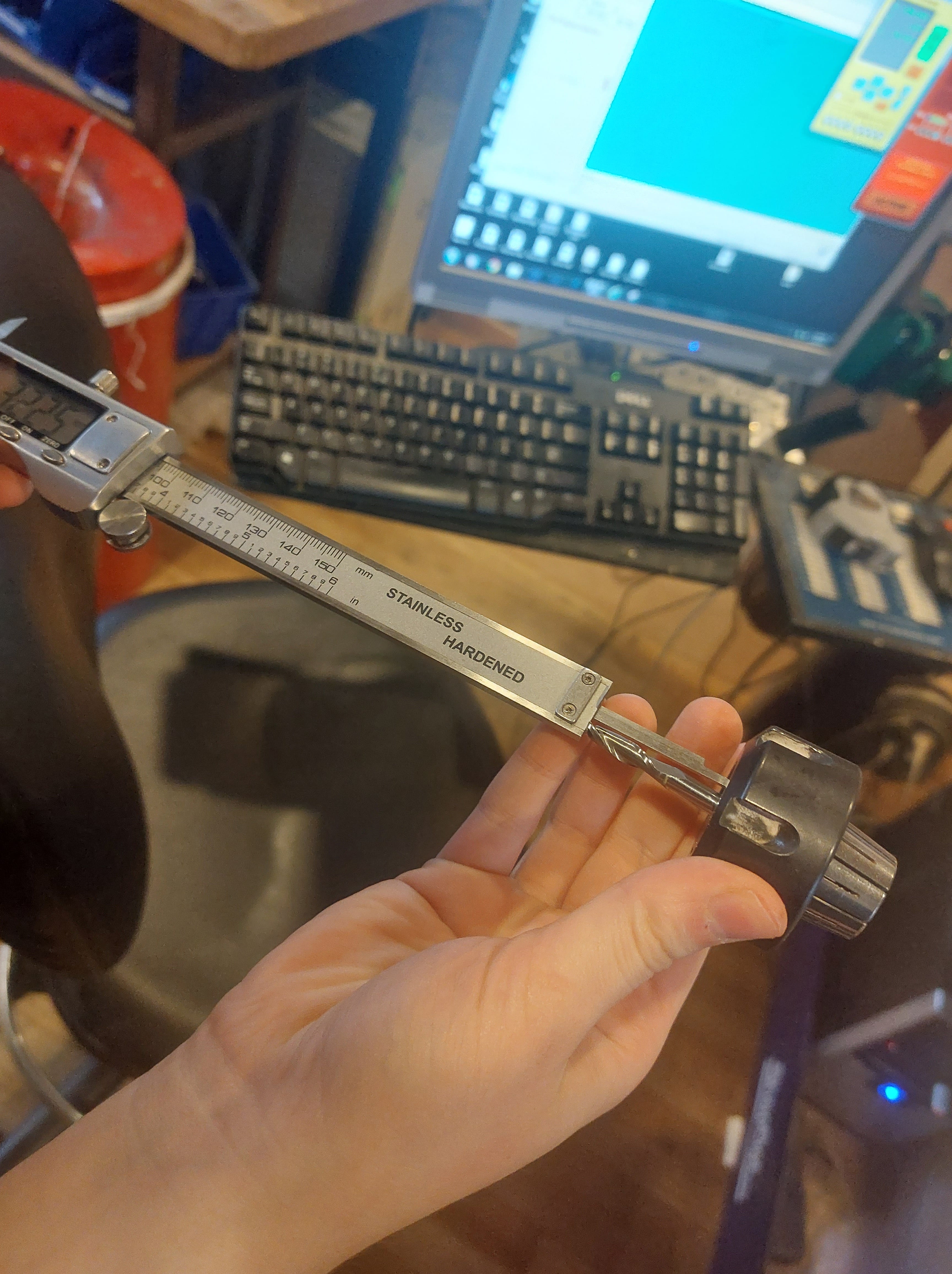
 milling bit in collet
- Place the milling bit in the collet until it alligns with the teeth inside the collet like shown above. Measure the length of the milling bit sticking out.
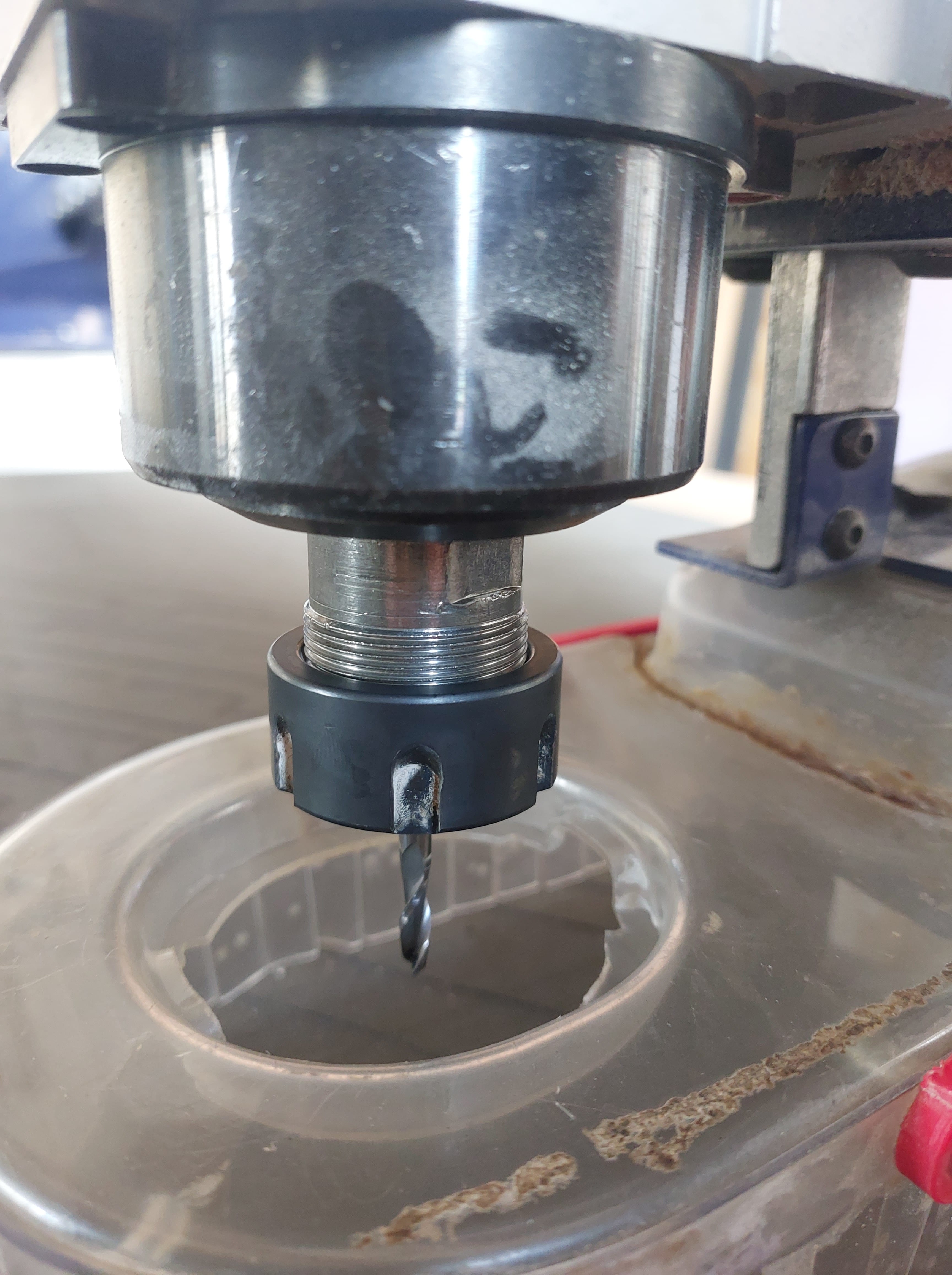
Re-assemble
-
Using the wrenches, screw the the clamping nut back into the milling head, with your chosen collet and milling head.
-
Bring the skirt back up and tighten the butterfly nut.
 reassembled
Open Vcarve pro
-
Open Vcarve pro on the computer
-
select OPEN NEW FILE
-
Within the JOB SETUP window on the left, there are a couple of things to look for:
-
JOB SIZE (x,y)
This represents the maximum extent the tool will move to on x and y axis. It is good to make these values the length and width of your material. The orientation of this should be the same as the material on the machines bed.
-
MATERIAL (z)
Enter the hight value of material thickness that you determined earlier. On the left, you can choose the ‘zero’ as either the bottom of the material or the top. Choose the bottom for jobs that will cut through the entire material, and choose the top for carve-in jobs.
-
XY Datum
Usually the left bottom corner is selected. This refers to the starting point for the milling, similar to the lasercutter.
-
Unit
choose mm
Save these settings by clicking OK.
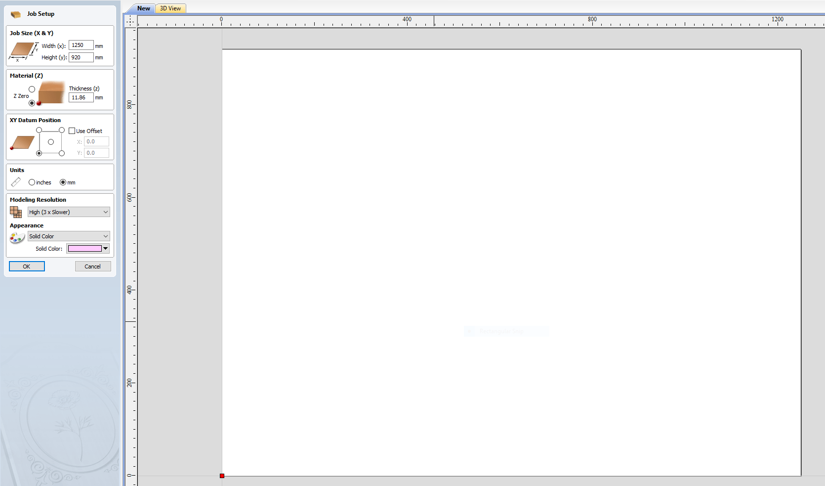 image of screen
DRAWING
-
Bring a previously made drawing in. The file types accepted are dxf, dwg, eps, ai, pdf, pvc, v3d, v3m, crv and skp.
-
Draw circles for where you want to place screw holes. These will later be used to attach your material to the sacrifical layer.
- FILLETS
- The thickness of the milling bit does not allow for a straight 90 degree angle cut in the POCKETS and INTERIOR profiles. This means that you need to add a T-bone or Dog-bone if you will use the profile to fit parts together.
- Save the file, the extension will be ‘.crv’
(image of screen)
CREATING A TOOLPATH
- The order of the toolpath creation should be: drilling pockets inner profiles outer profiles Everytime you make a change, hit calculate in the TOOLPATH window afterwards.
Always use climb as a beginner.
(image of screen)
DRILLING TOOLPATH
Define:
- START DEPTH (D): 0mm
- CUT DEPTH (C): 2mm (this is purely to indicate where the screws will go)
- TOOL: Select a tool from the preset tools. If you do make changes, click on EDIT and not SELECT so that the original setting stay the same
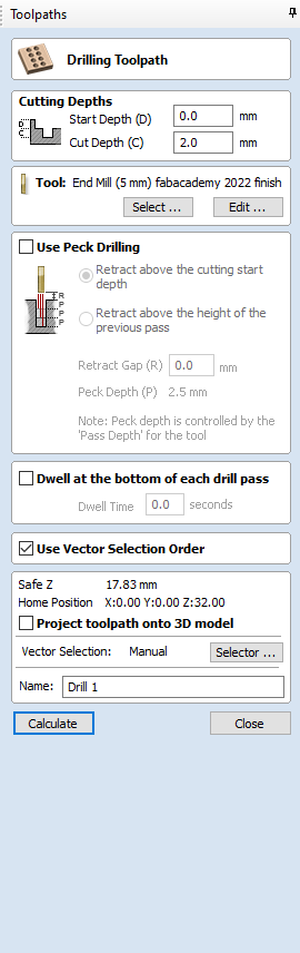 image of screen
You want to make sure the milling bit and collet you intend on using matches what is defined in the settings for each toolpath, like below:
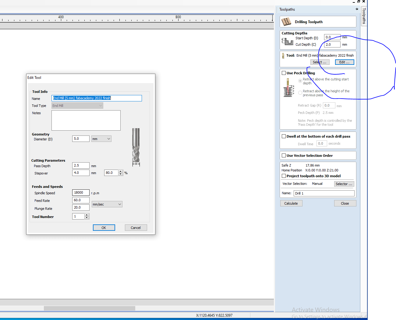 defining the milling tool
At the bottom of the window, give it an identifiable name.
POCKET TOOLPATH (raster)
Define:
- START DEPTH (D): 0mm
- CUT DEPTH (C): decide how deep you want this pocket to be (e.g- 5mm)
- CLEAR POCKET: raster
- CUT DIRECTION: conventional
At the bottom of the window, give it an identifiable name.
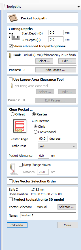 image of screen
POCKET TOOLPATH (offset)
Define:
- START DEPTH (D): define as the CUT depth of your POCKET TOOLPATH raster (e.g- 5mm)
- CUT DEPTH (C): define how deep you want this pocket to be, working downwards from above START DEPTH
- CLEAR POCKET: offset
- CUT DIRECTION: conventional
At the bottom of the window, give it an identifiable name.
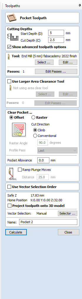 image of screen
PROFILE TOOLPATH (inner profiles)
Define: - START DEPTH (D): 0mm - CUT DEPTH (C): the thickness of your material
- MACHINE VECTORS: inside/left (what does this refer to?)
- CUT DIRECTION: climb
TABS: In order to get this inner profile out of the material easily, you add tabs to the toolpath. Place these on the shape of your cut. check the box for adding tabs to toolpath - LENGTH: 5.0 mm - THICKNESS: 4.0 mm
At the bottom of the window, give it an identifiable name.
(image of screen)
PROFILE TOOLPATH (outer profiles)
Define:
- START DEPTH (D): 0mm
- CUT DEPTH (C): the thickness of your material
- MACHINE VECTORS: outside/right (what does this refer to?)
- CUT DIRECTION: climb
TABS: We use tabs to keep components secure during the jobs, otherwise it will move around - atleast two, otherwise every 20-30cm You add tabs to the toolpath. Place these on the shape of your cut
check the box for adding tabs to toolpath
- LENGTH: 5.0 mm - THICKNESS: 4.0 mm
At the bottom of the window, give it an identifiable name.
(image of screen)
SAVE TOOLPATHS
- The file type for Shopbot 3 is ‘sbp.’
- Save the drilling tool path seperately from the rest. This is because you will first do this job (marking where the screws will go) and drill in the screws to secure your material on the sacrificial layer. Only then will you continue with the rest of the jobs.
(image of screen)
Prepare yourself
- put on the safety glasses and safety earmuffs, and keep on as long as you’re running the machine.
 emergency shut down button
Go into Shopbot 3
-
Open Shopbot 3 back up
-
Move the milling head (using the arrows) to where you want the new XY ORIGIN to be.
-
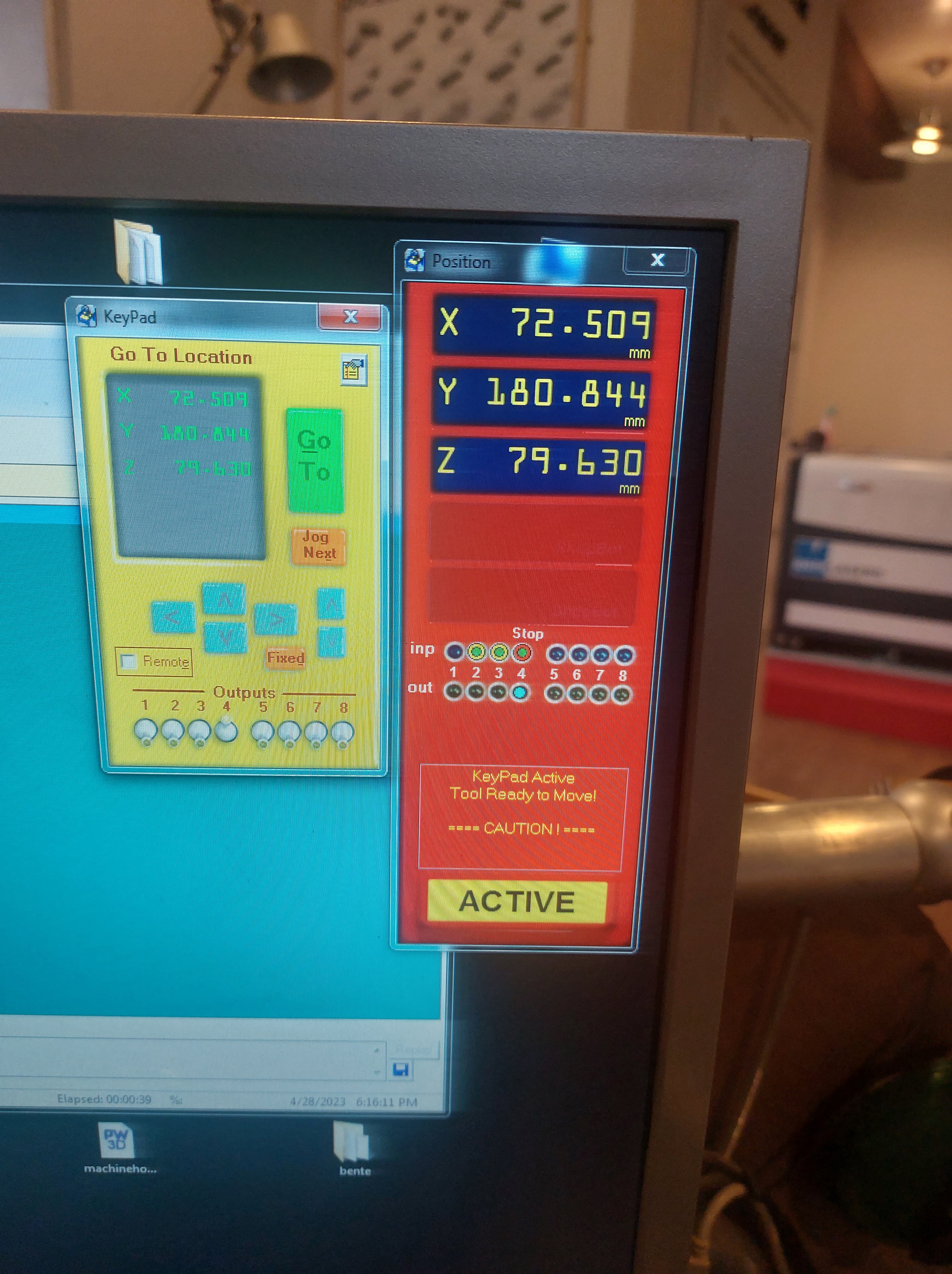
Take a photo of them (visible in the POSITION window) or write them down, in case something goes wrong and you have to stop the job. You can then start it up again from the same starting point.
-
In the dropdown menu ZERO, click on ZERO(2)AXES (X & Y). This will save the coordinates as the job’s origin. In the POSITION window, these coordinates are visible.
-
Move the milling head above a clear surface on the sacrificial layer.
-
Pick the metal plate stored at the top of the milling head and touch it to the end of the milling bit. Touching the metal plate to the bit should close an electric current.
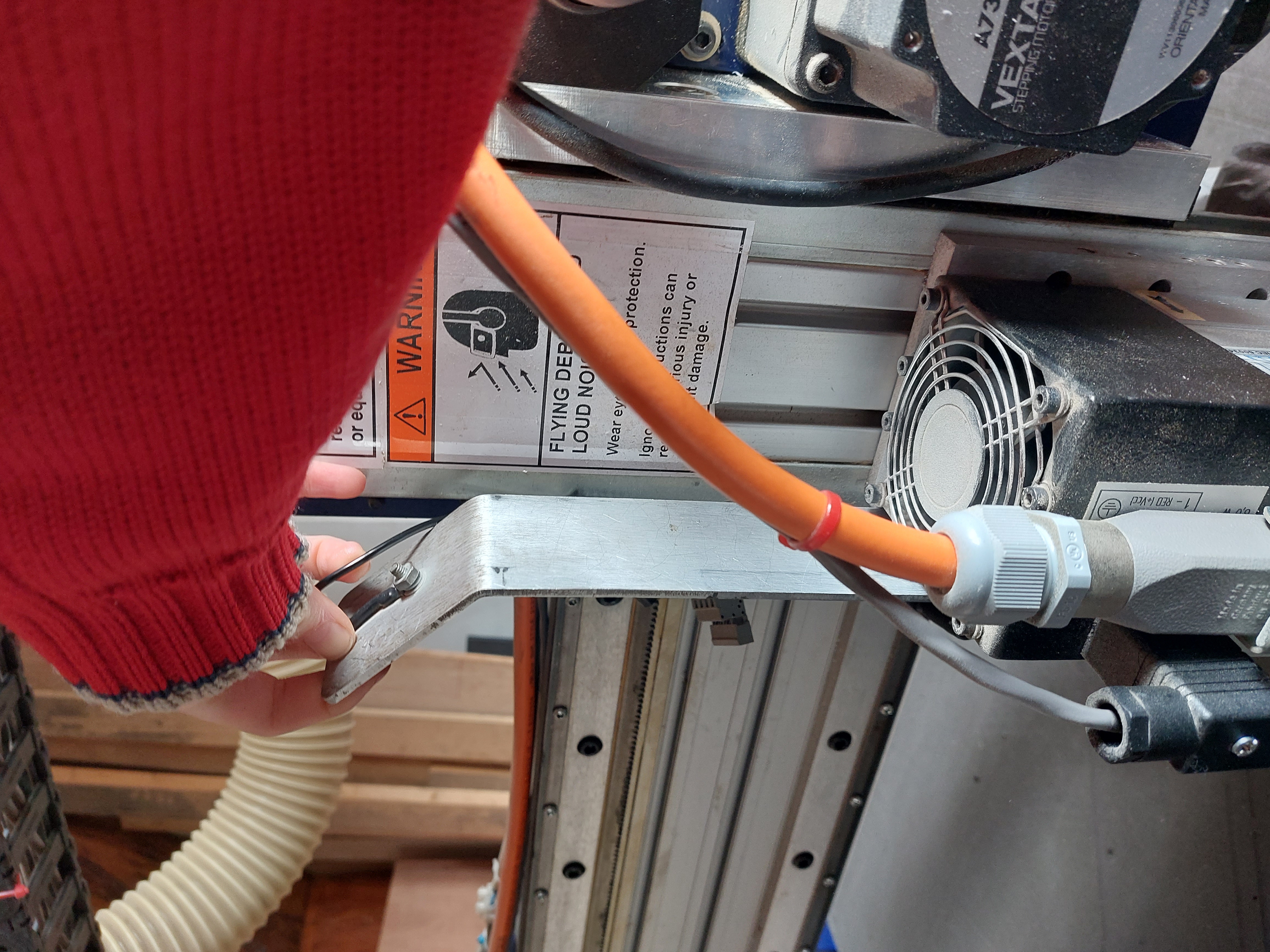 where to find metal plate
If the current closes, within the POSITION window the left-most ‘STOP’ INP CIRCLE should turn green.
- Repeat this a couple of times to make sure the current is closed.
These steps are important because the Z-axis will automatically move down and it should stop when the metal plate touches it (it being the material or the milling bit?)
- Put the metal plate under the milling bit on the sacrificial surface.

- Press the button ‘Z ZERO’ in the top toolbar.
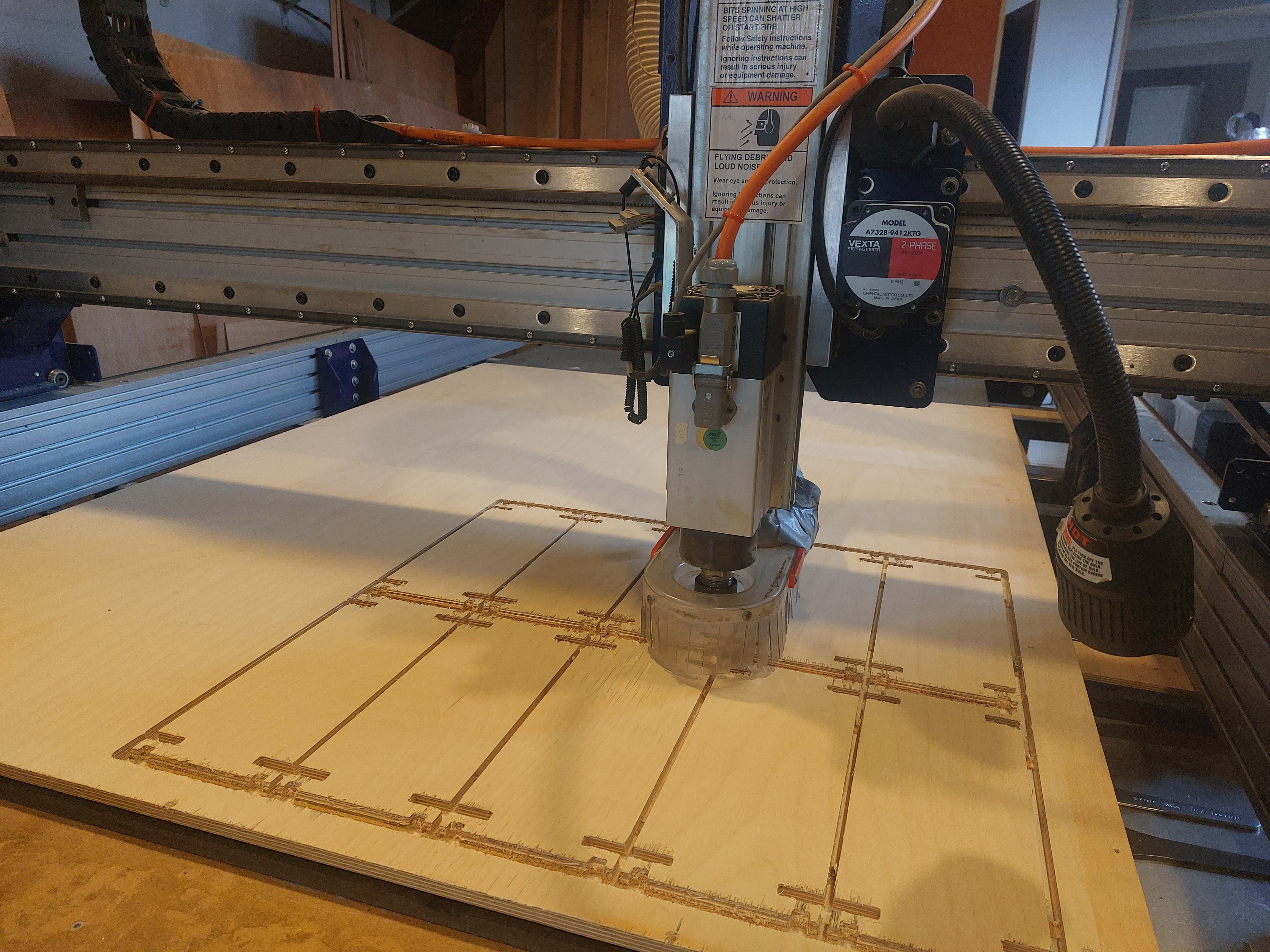
Start milling job
-
Load the drilling toolpath by pressing the LOAD PART FILE in the POSITION window.
-
Turn on the ventilation and give it a minute to fully gain its power.
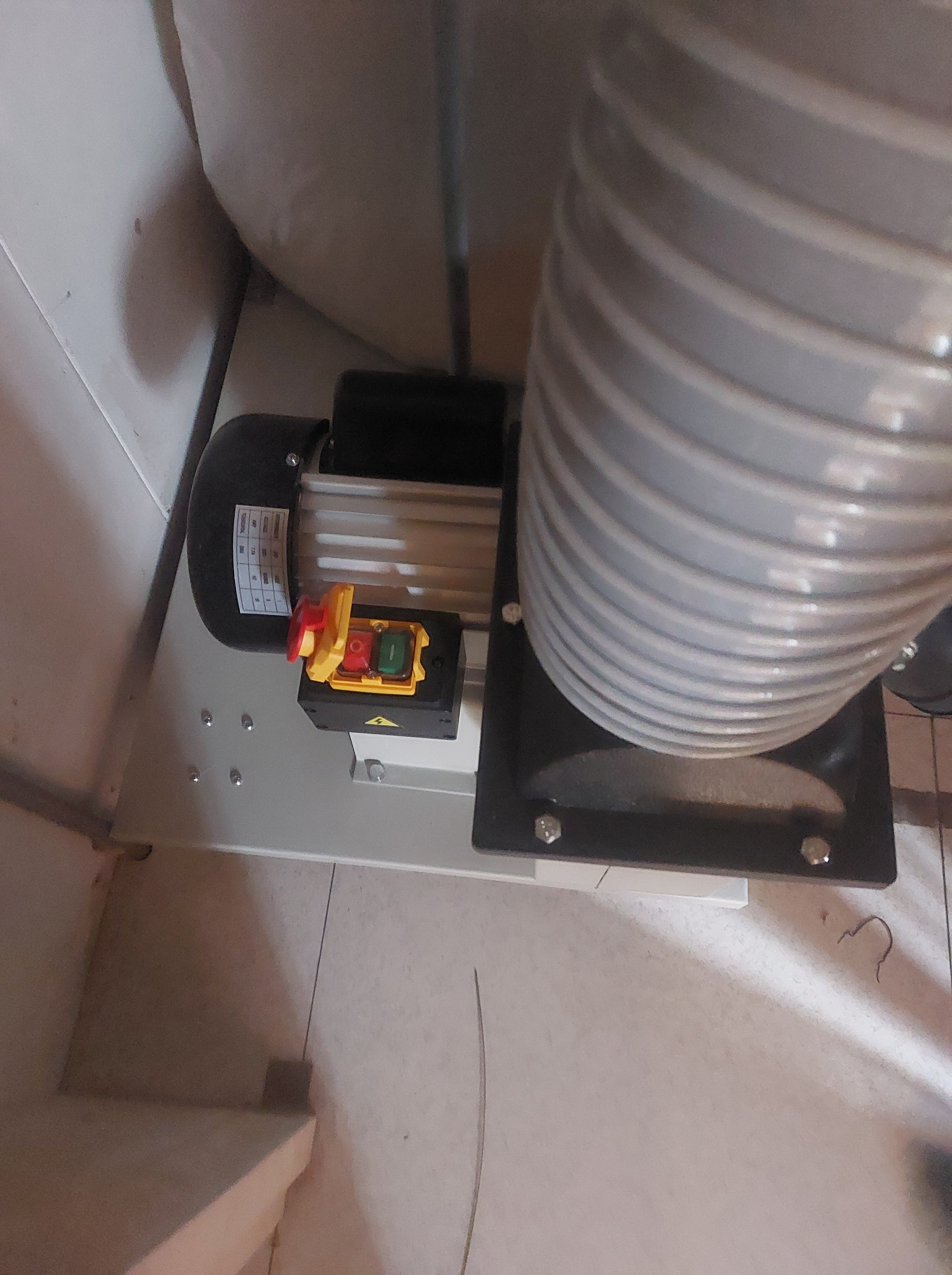
-
Put the key attached to the wrench in the keyhole found underneath the machine’s ON/OFF knob and turn it. The milling bit should start turning.
-
On the varispeed box, manually define the spindle speed to 18000.
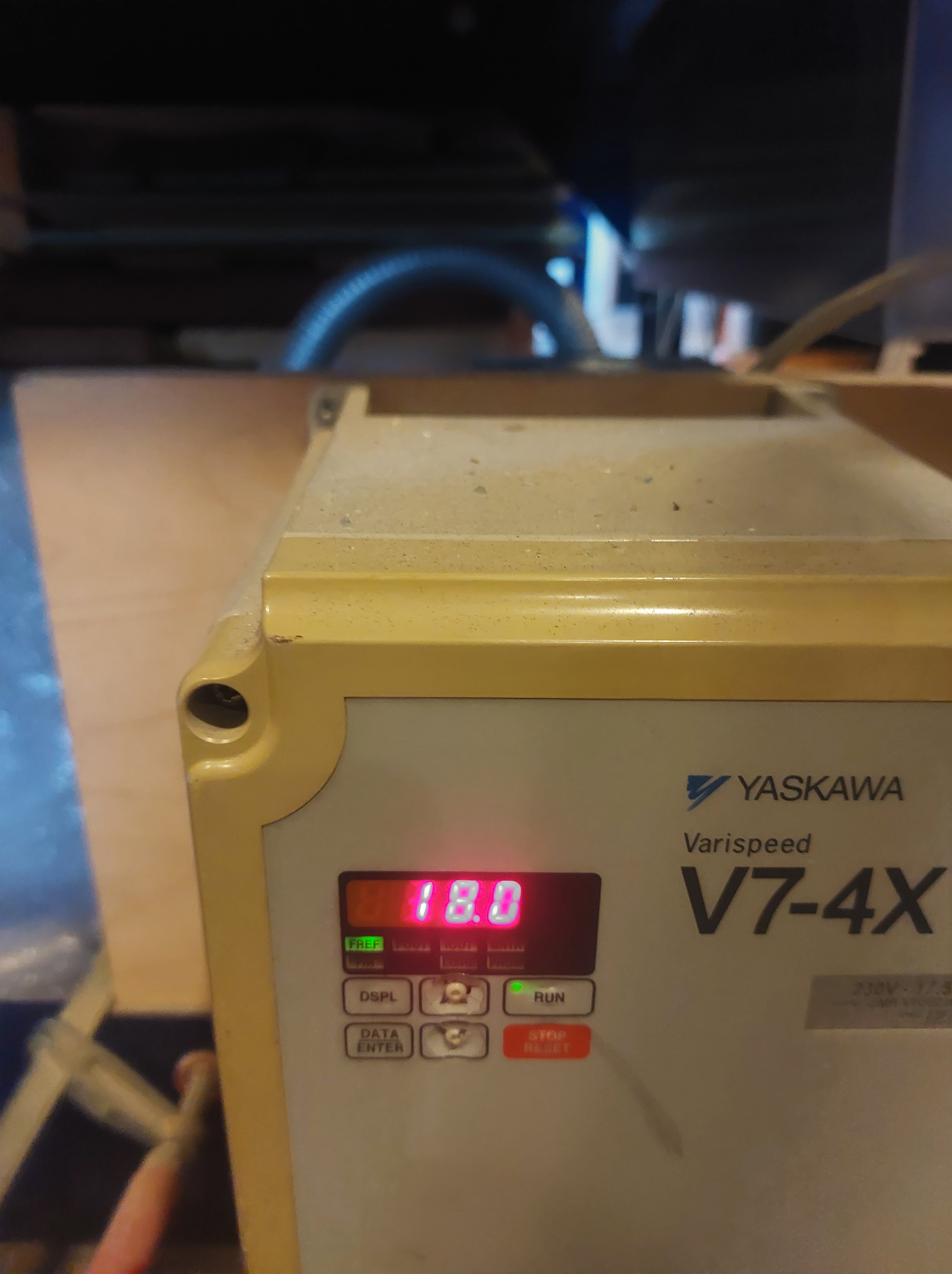
-
Face back to the screen in Shopbot 3, and press START (dont change anything). Until you know for sure that it is going well, keep your hand hovered above the spacebar on the keyboard. If necessary, pressing it will pauze the job.
-
Once the drilling job is finished (which will have created pockets), move the milling head with the arrows to the back so you have access to the material.
GOOD TO KNOW!
The machine does not know the end limit of movement on the x,y, and z axis, and if you assign it to move beyond them it will try to do so. Although it can’t, it will think that its position is further than it is. So when you move the milling head up before you move it backwards in the step above, only do so much that is necessary! Otherwise you will have to recallibrate the z-axis.
-
screw the material onto the sacrificial layer at the indicated points.
-
Load the toolpath for the rest of the job, and hit START once more.
-
When the job is finished, use the arrows on the keypad on the screen to move the milling head away.
Post-processing
-
Turn off the ventilation and the CNC machine.
-
Unscrew your material off the sacrificial layer and move it away from the bed of the machine.
- Clean around the machine for the next user, and use a vaccuum if necessary.
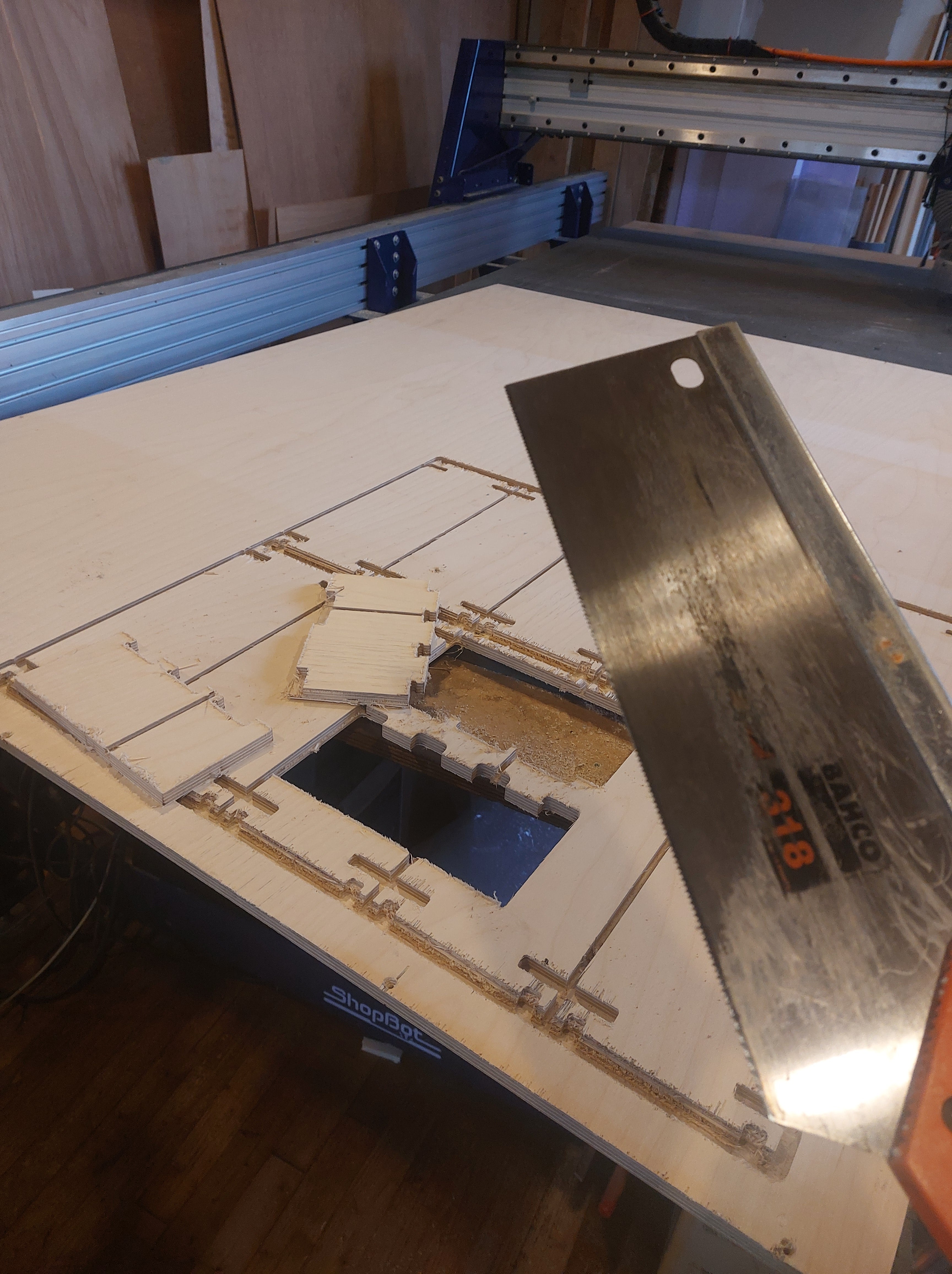
- Saw the tabs you designed around the cut shapes to remove them from your sheet material. This is prefered over breaking them out, seeing that can lead to the wood splintering.
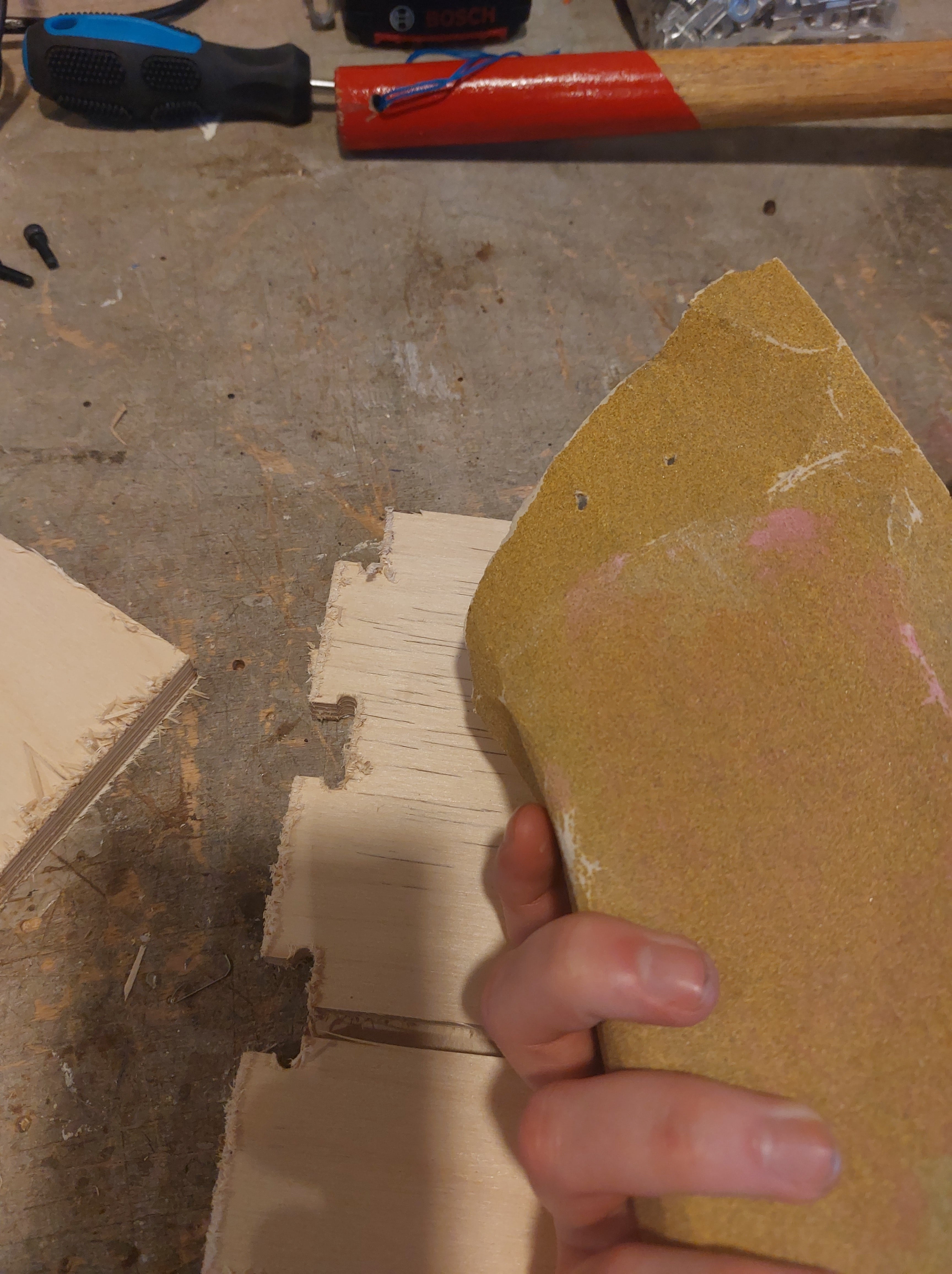
- If you want, you can sand irregularities around the milled parts with sandpaper available at the station.
dont worry be happy