How to: Make a pressfit comb
Kerf Correction
When using a laser cutter to makes cuts in whatever material, there is a portion of that material that gets burnt away. This is referred to as the laser Kerf and can range from 0.08mm to 1mm of material that is lost in the process. It is recommended to keep the minumum cut width no smaller than the thickness of the chosen material.
I am going to be making a PressFit comb before making the box. This is important because I need the finger joints to sit snug so I don’t need to use glue for example to keep it together. This is not an exact way of determining the laser Kerf, but fitting for my context. To determine the exact laser Kerf, check out these links :
Making a Press Fit design
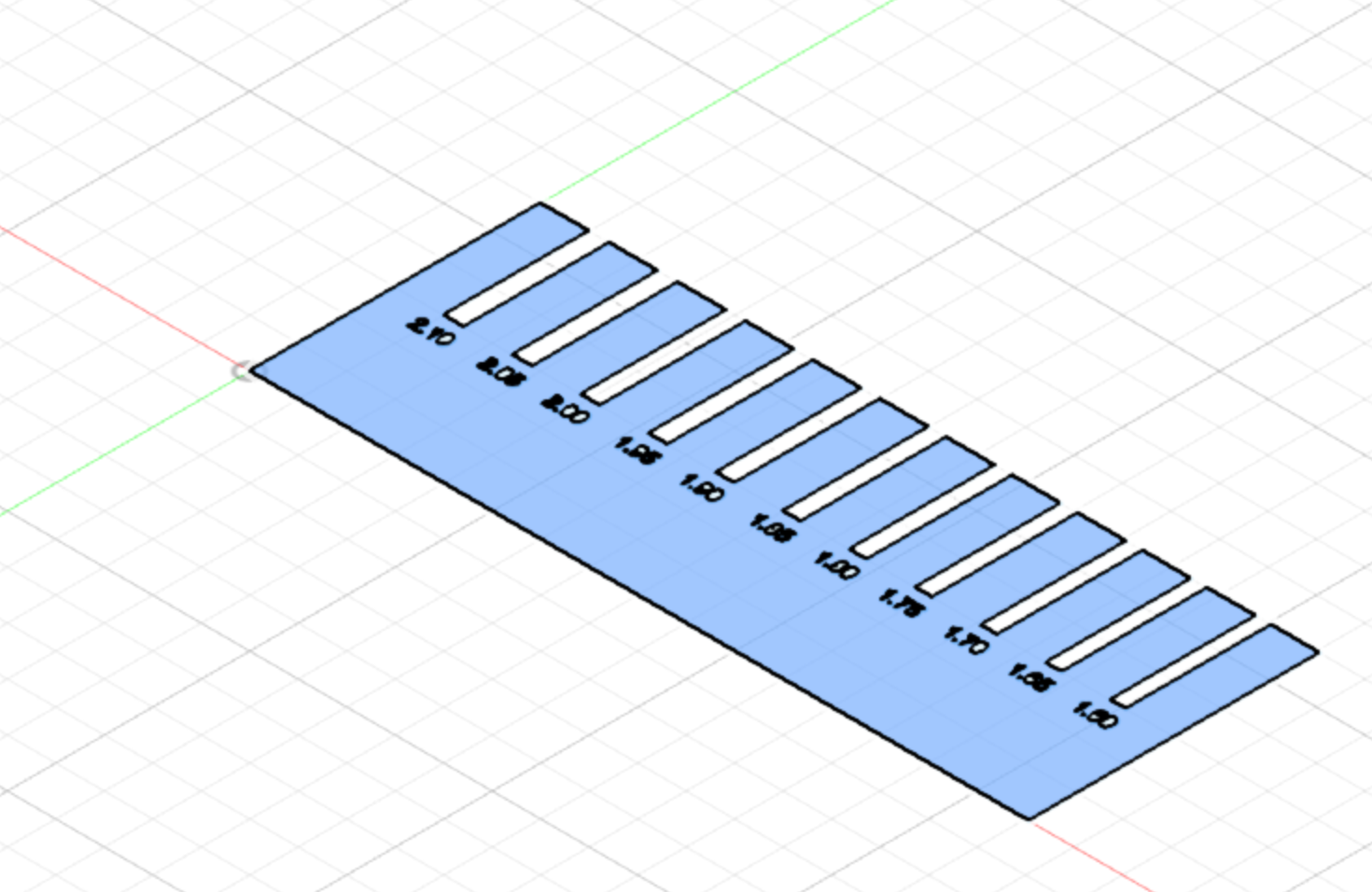
Before making a box out of plexiglass to keep my circuit boards safe, I want to determine the Kerf correction of the material. This PressFit, also known as a joint clearance comb, is a tangible way of finding the right values for your finger joints depending on the type of material you are using.
A Working in Fusion 360
This software is useful for parametric design, so I decided use it. I initially used Illustrator but seeing it is not meant for this type of projects it became very unnecessarily complicated. On a different page of this site I document me learning how to use this software, with basic experience of 3D modelling.
Step 1 : base
-
Make a new component
-
Start a new sketch, and use the 2-point rectangle tool to make a 30x100mm
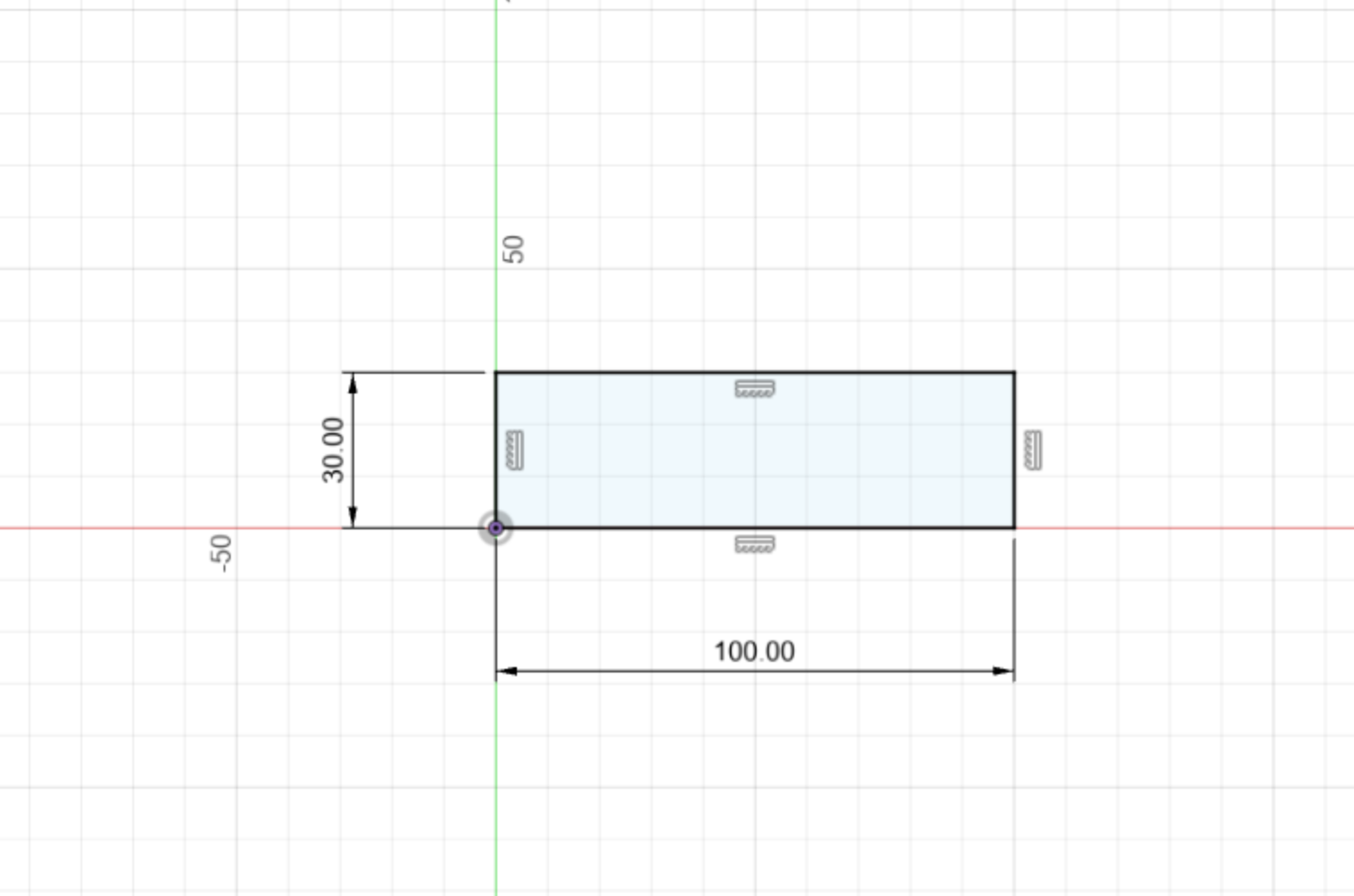 (image of sketch)
- Extrude with a thickness of 2.1 mm (to match that of the material)
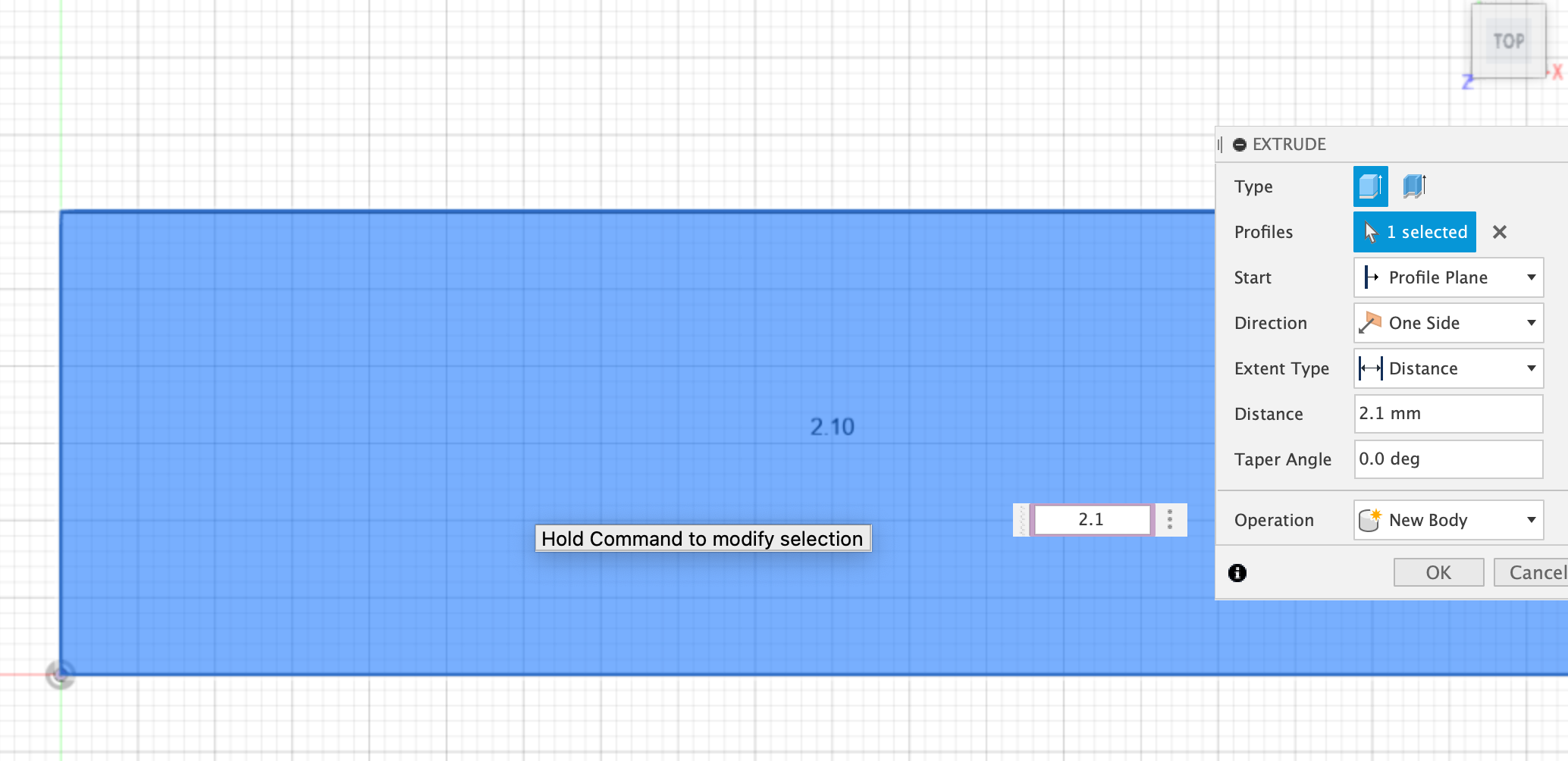 (image of extruding base)
Step 2 : first cut
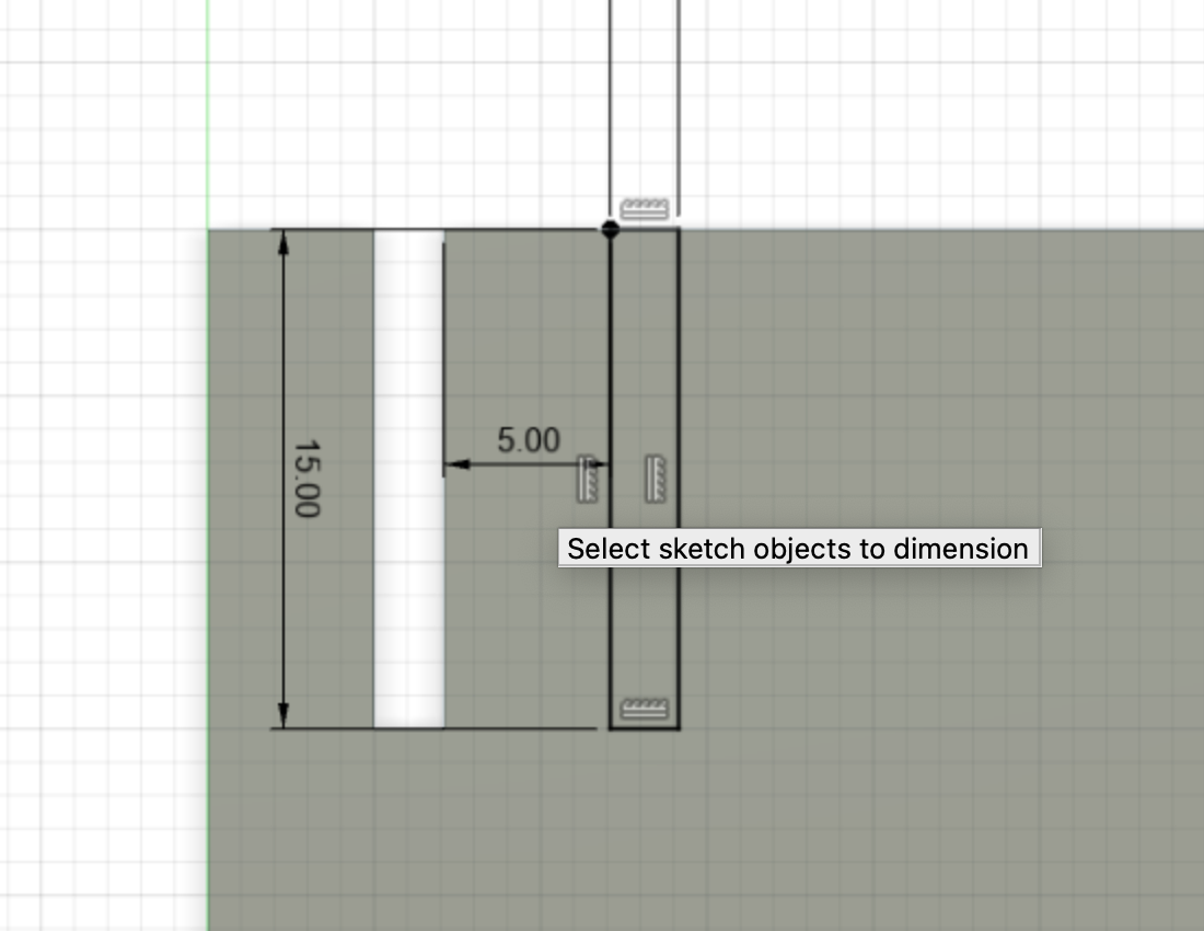
- Make a new sketch, using the 2-point rectangle tool again and this time the [ first variable of the press fit x 15.0mm ] = 2.1 x 15.0 mm
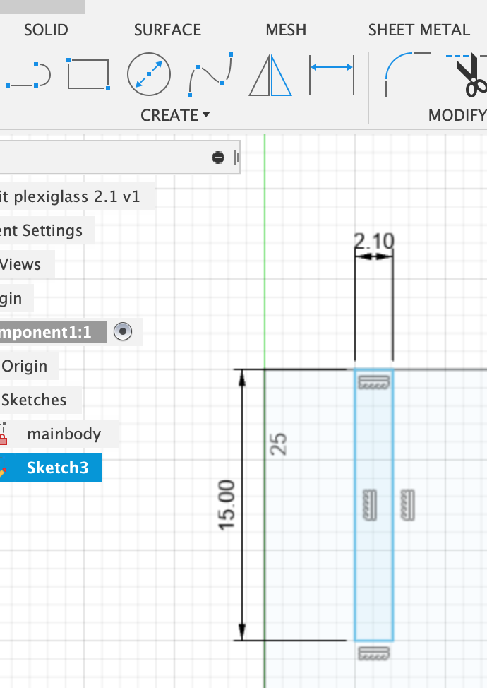
- Use Sketch Dimensions in the toolbar to space out 5mm from the left of the base sketch
(image where to find sketch dimension tool in bar)
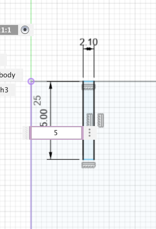 (image of position sketch 2)
Step 3: cut out all values
-
continue this process until you have all potential thickness values cut out on your PressFit (in my case values 2.1-1.65mm) with 5mm intervals
-
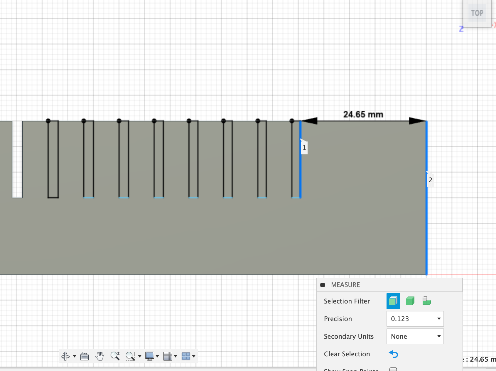
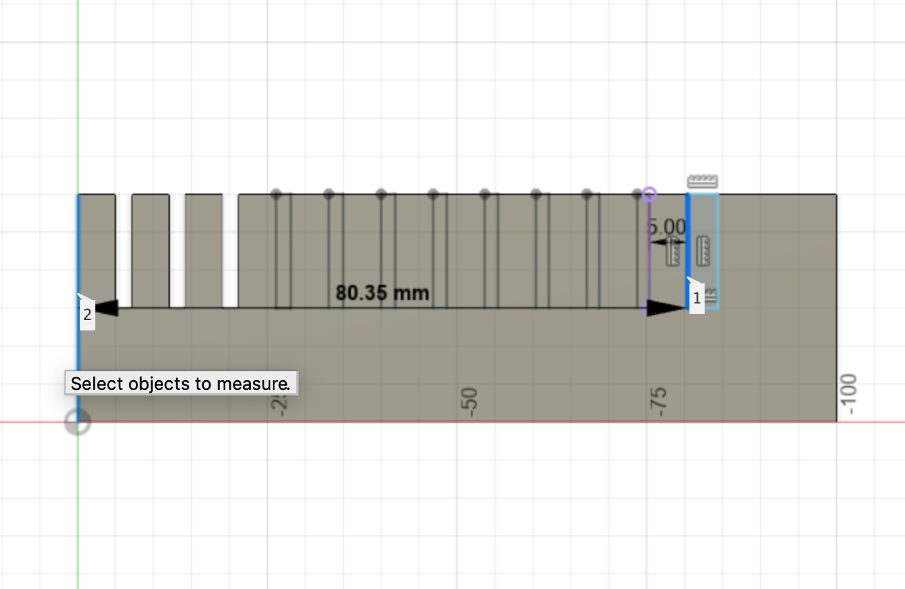
I ended up with quite some space left on the end of my PressFit, once all the values had been cut out. I chose to measure the length of the PressFit up until the end of the last cut, added 5mm to that, and changed the full length of the base to that in order to safe on material.
 (excess space on base)
 (change of sketch dimensions)
Step 4: exporting the file to Lightburn
We now need to make a file readable by Lightburn, (the software for our lasercutter) out of our 3D model. For this part, I followed parts of this tutorial .
Step 4a: all elements into single sketch
-
We want to project all of the edges into a single sketch. This will make it possible to quickly export the sketch as a DXF file.
-
Make a new component. This is helpful for when you want to copy the file into another design. Give it a distinct name.
-
Start a new sketch, and choose the bottom origin plane (as long as that is the plance your design is on)
-
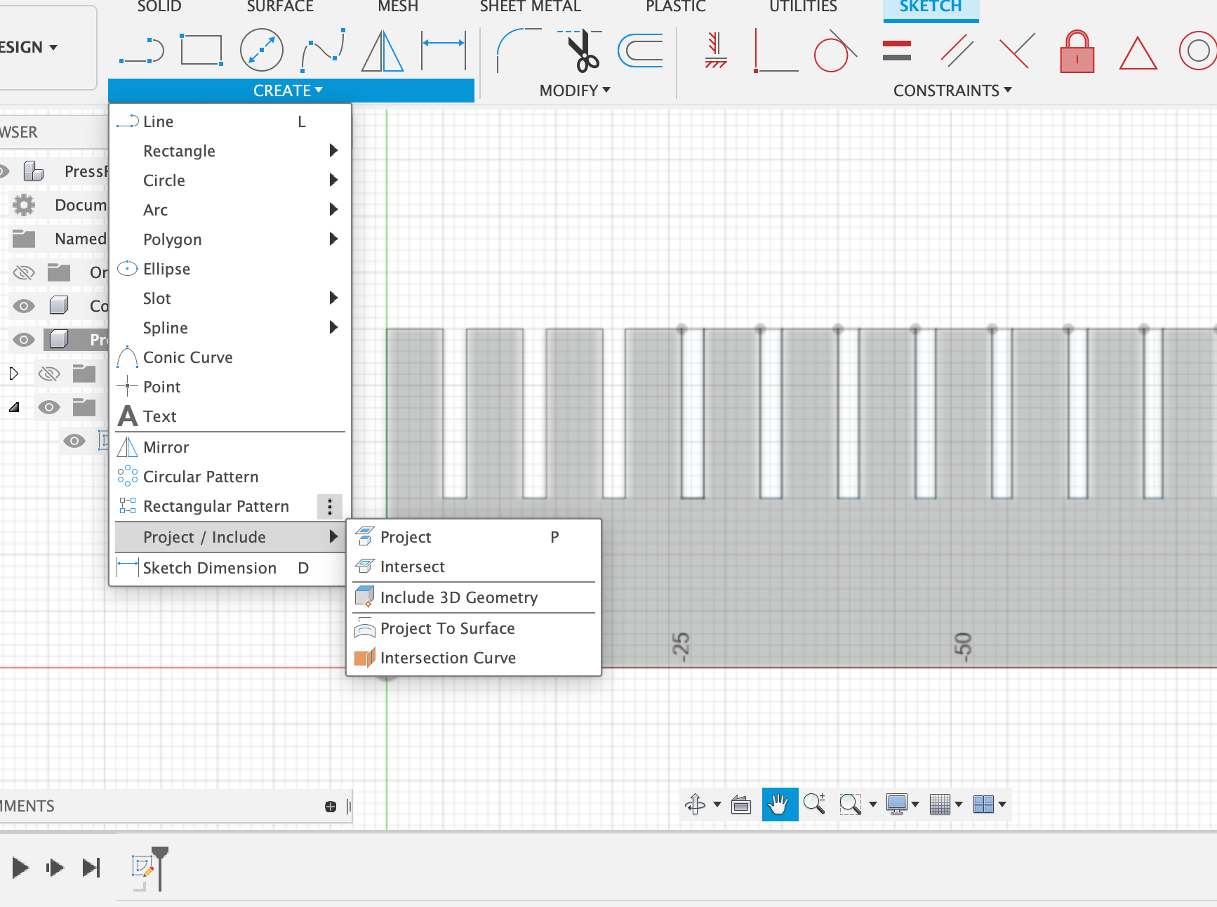
Under the dropdown toolbar CREATE, go to Project/Include and select Project
 (image toolbar dropdown)
This tool enable you to project bodies, edges or sketch objects onto the active sketch plane (the sketch we just started)
- A new dialogue called Project will appear. Within this you can choose to select through Specified Entities or Bodies. I used Specified Entities because I noticed my text wasn’t being included in the projection. Make sure all your elements are selected if you do so.
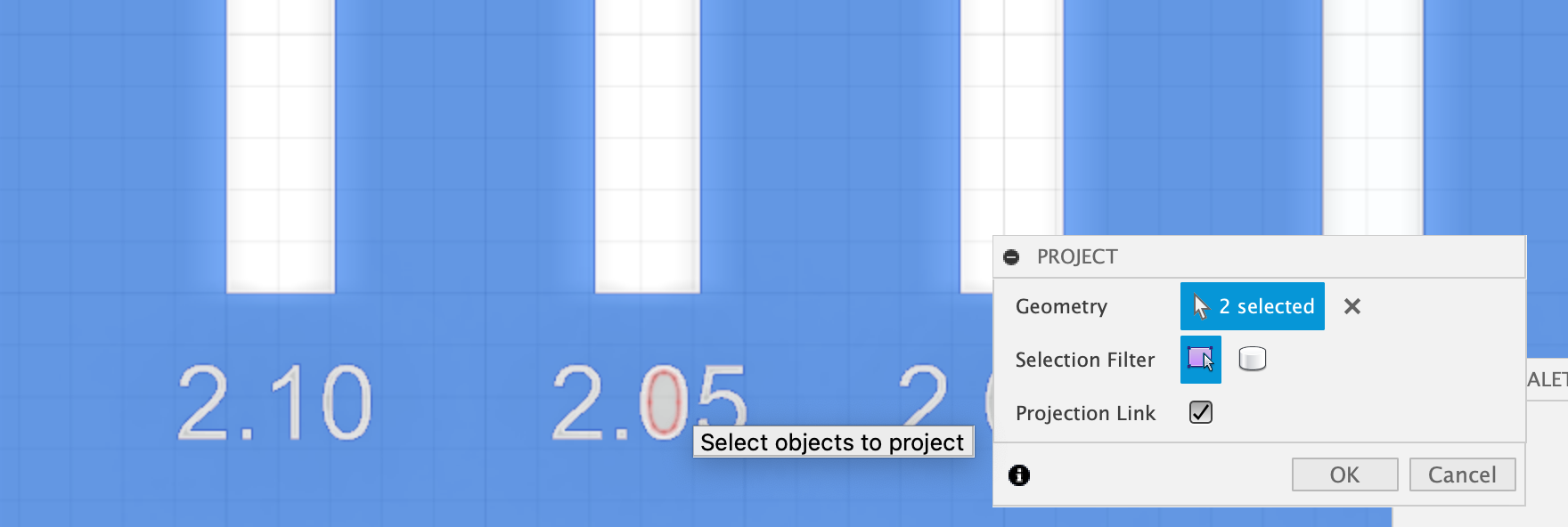 (image toolbar selection bodies projection)
-
In the dialogue there is a checkbox for Projection Link. If it is checked, the sketch will remain linked to the original source. This means the sketch will automatically update and adapt to any changes made to the 3D body it is projecting. Click okay.
-
Its a good idea to then make all components and sketches invisible, except for the projection sketch. You can then see clearly if all the necessary elements have been projected.
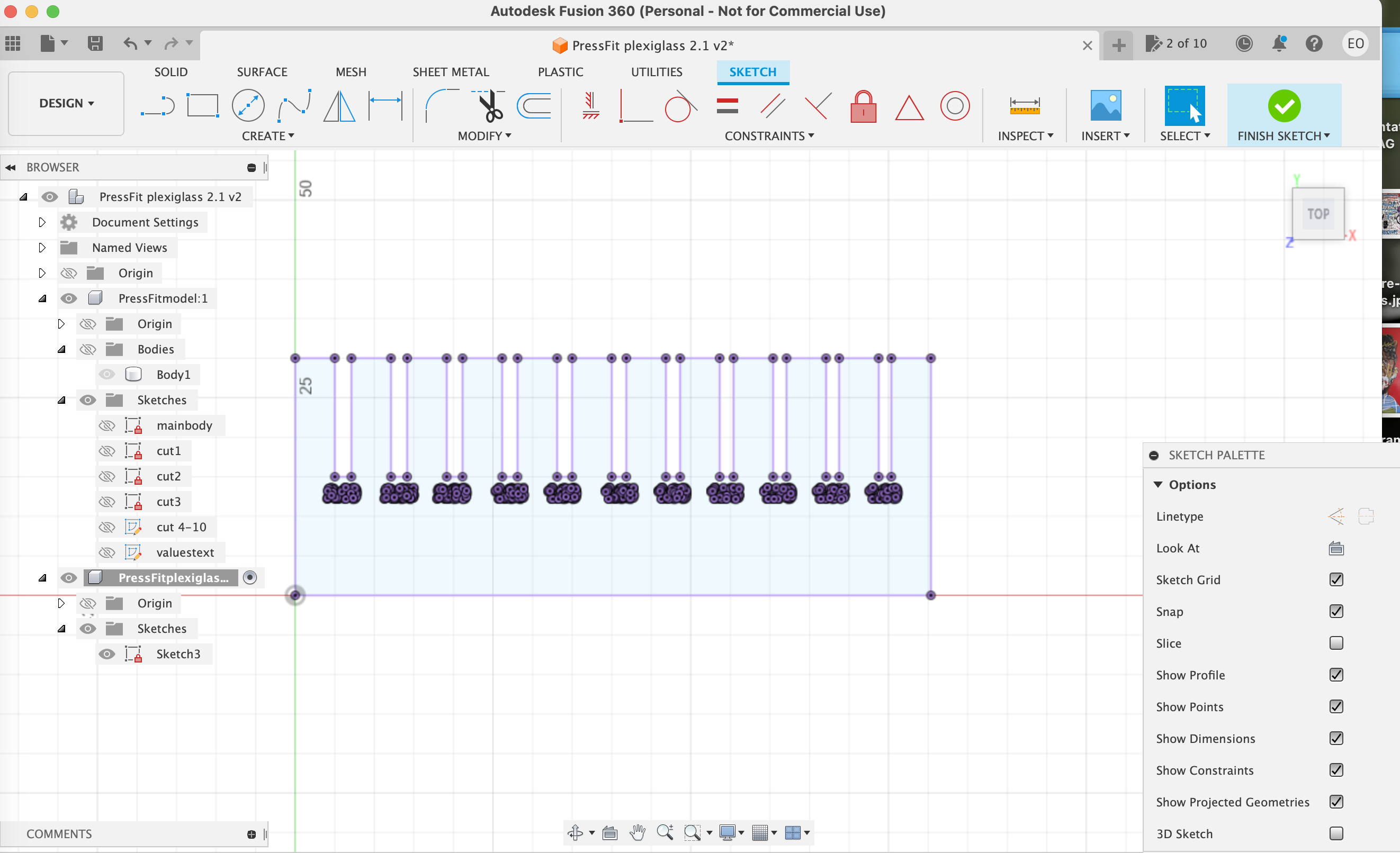 (image of sketch with everything else made invisible)
- I am going to be engraving my text onto the model, but if you are planning on cutting out text you have as well, follow this tutorial . You are going to have to alter the design of the text in consideration of the ‘negative space’ or ‘islands’ within certain characters.
Step 4b: Exporting DXF file
- DXF
- Drawing Interchange Format
- common file type used by CAD (computer aided design) and various software packages
- can be used in vector formats, which allows CNC machines to follow their 2-dimensional paths
- similar to DWG files, but more compatible with other software packages since it is openly documented
- originally created by Autodesk
- Toggle open the Components and Sketches folder, and give the last sketch you made an identifiable name
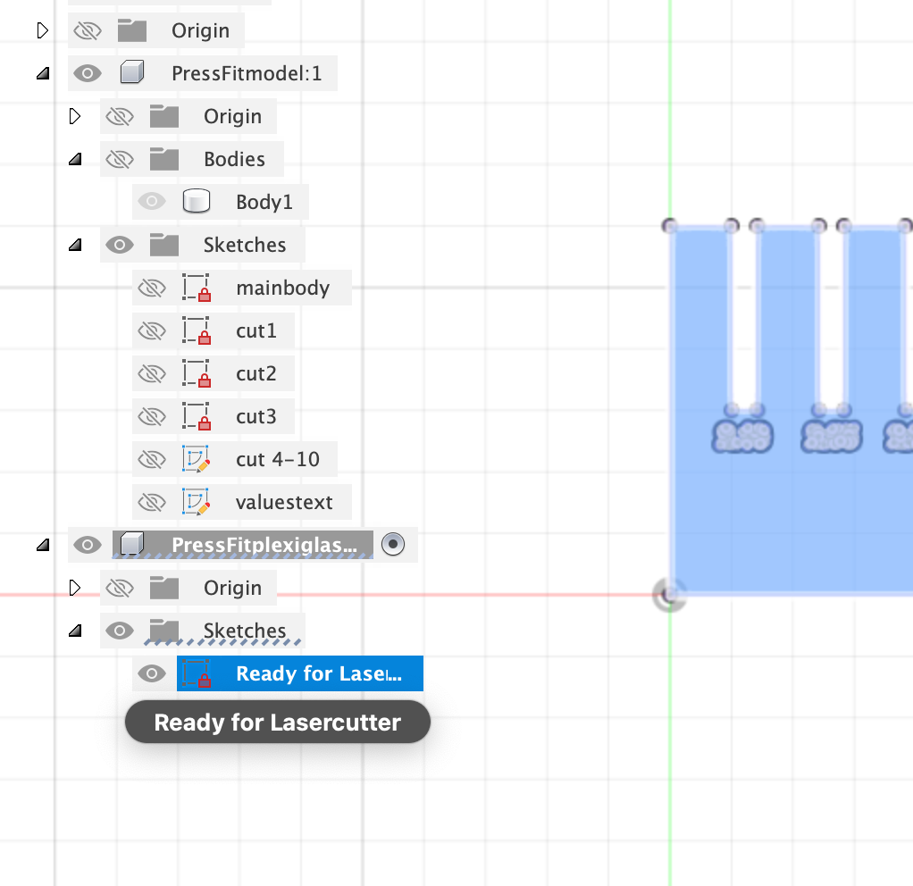 (image with toggled folders and name change)
- Click ‘save as DXF’ and give it a useful name and location on your laptop
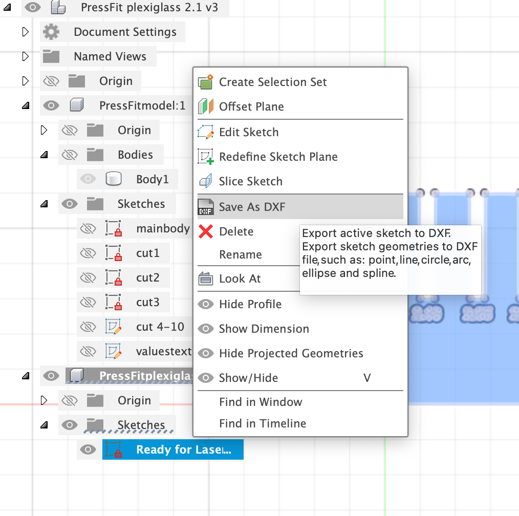 (save as DXF option)
- It is useful to then open the file you just made in Fusion 360 or another software, to double check that everything that has been included, contours are closed etc
 (image of DXF file imported in Fusion360)
-
There is also a possibility in going through the standard exporting option and selecting DXF as the format, but it will then export all the sketches in the file. It is safest to export individual sketches, to avoid messy or corrupt files
-
You are ready to cut!
For this PressFit, I used the following values for the lasercutter:
cutting SPEED: 10 POWER: 50
engraving SPEED: 100 POWER: 25
NOTE: the engraving turned out okay, but not great. Although it didnt go too deep, because it is text there was a lot of inconsistency. Keep in mind that text that small might not look great on white acrylic.
For importing your DXF file to Lightburn and working with our lasercutter, see my lasercutting_page
(image of pressfit printed)
The value that fit most sturdy without there being too much friction which could lead to breaking, was 2.7mm.
To find out how you can use this information for making a finger joint box, see my Acrylic Box page