Learning how to work with Fusion 360
- Fusion 360 is a commercial software application developed by Autodesk that can do:
- computer-aided design
- computer-aided manufactoring
- computer-aided engineering
- printed circuit board design
My background lies in Blender, Unity and Adobe softwares. I have never worked with Fusion 360, and plan to use it for parametric designs for our Fablab machinery. On this page I will be keeping track of my initial learning of this software application.
Shortcuts
E = extruding
C = circle sketch
Making a toy block
-
Go to your preferences in the top right corner, to check that your environment is set in default settings. Once the menu is opened, in the bottom left corner there is a corresponding button. If it is shaded grey you can continue. Keep the menu open.
-
You are going to want to do this with you units as well. On the left side, you will find a Default Units tab, and under design you can choose your units. I am going to be working in millimeters (mm). Remember to save changes when you exit the dialogue. If you want to change units within an individual file, you may do so in the Fusion 360 browser in the top left of your environment under document settings.
When making a new part of your model, create a new component in the middle of the tool bar. This will help keep everything organized. The type will always be standard, unless working with sheet metal.
- For most workflows, you start with a 2D sketch that is turned into a 3D body.
- It is best to sketch 2D from an orthographic/front view (which is what your environment automatically turns into when starting a new sketch)
Always start sketching at origin, this will help with constraints and dimensions
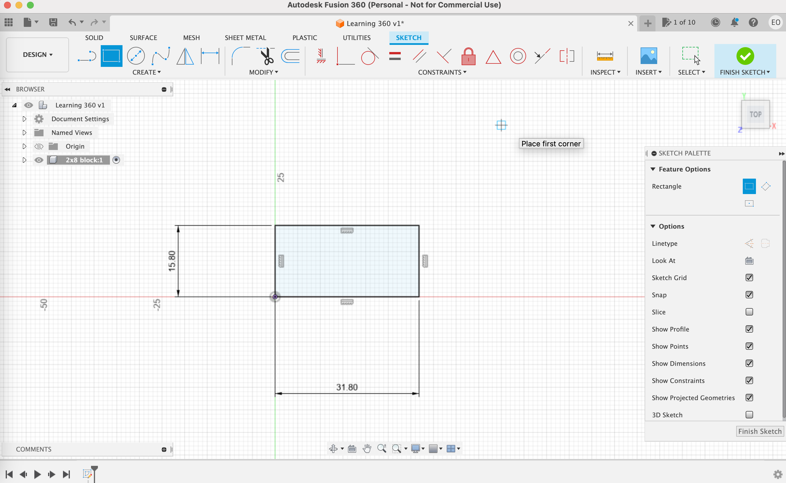 (screenshot of 2D sketch)
-
Going from 2D sketch to 3D body, is easily done with the extruding tool found in the SOLID tab of the tool bar.
-
Use the home button in top right viewport to see the model in 3D.
-
Both the sketch and 3D body are visible in the folders within the browser
All development is recorded at the bottom of the environment. This allows you to go back and make changes, as well as delete features. Fusion 360 is cloud-based, meaning files are stored within Autodesk servers and not your local computer. Therefore it is important to save throughout your workflow.
- To limit the degree of freedom of a 2D sketch, use sketch dimension in the tool bar.
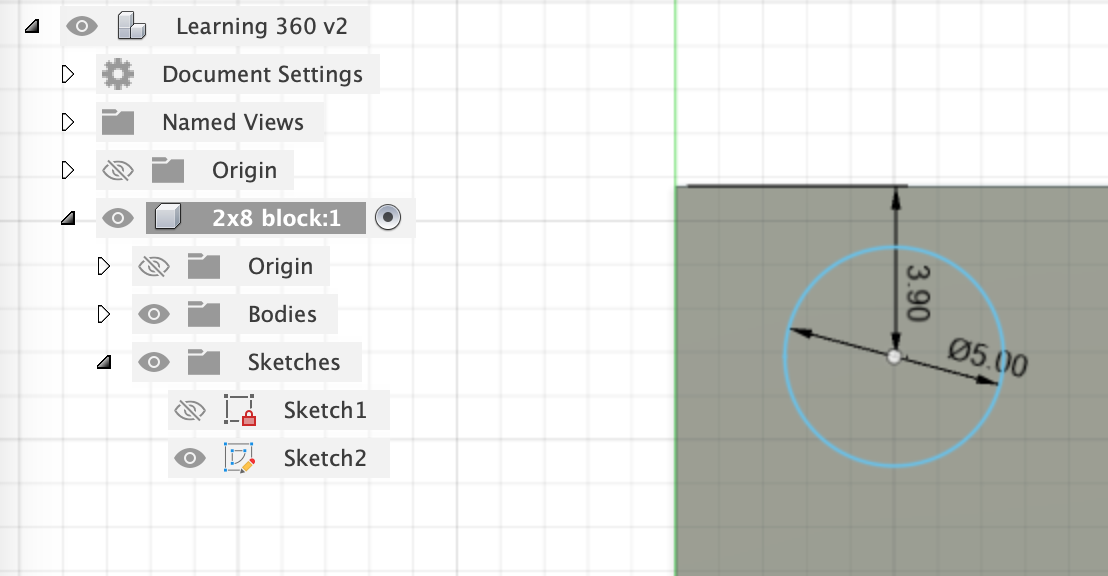 (image of circle dimensions)
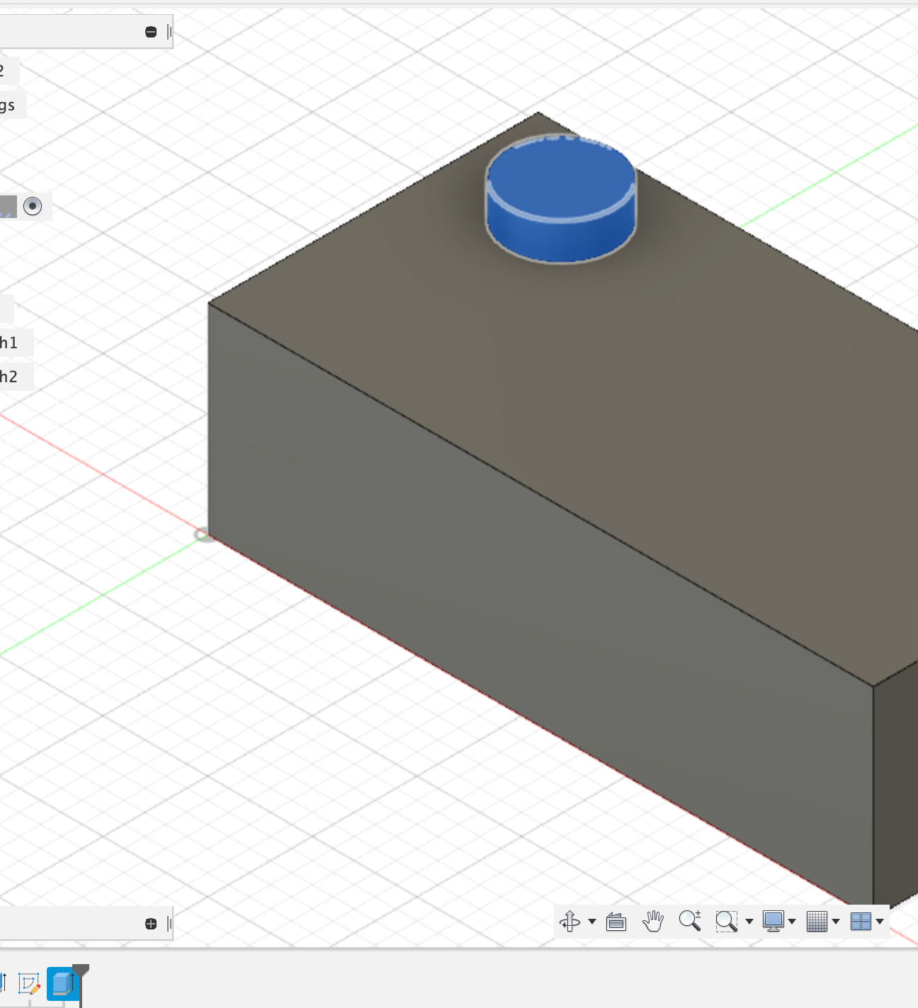
- When extruding from a sketch on an existing 3D model, you will see in the Operation on the left that it is set to JOIN. This means the extrude will join the existing 3D body.
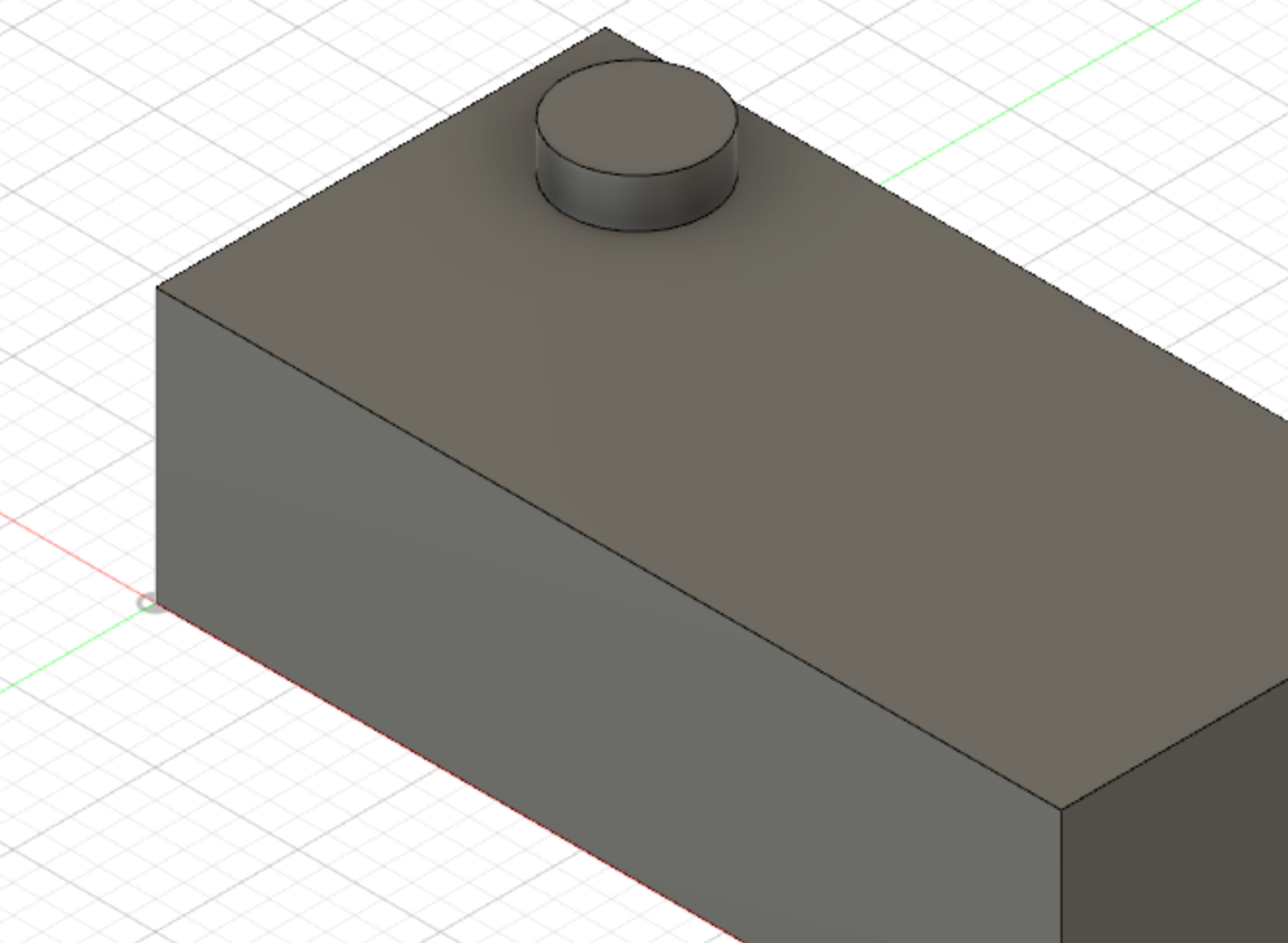 (image of cylinder on cube)
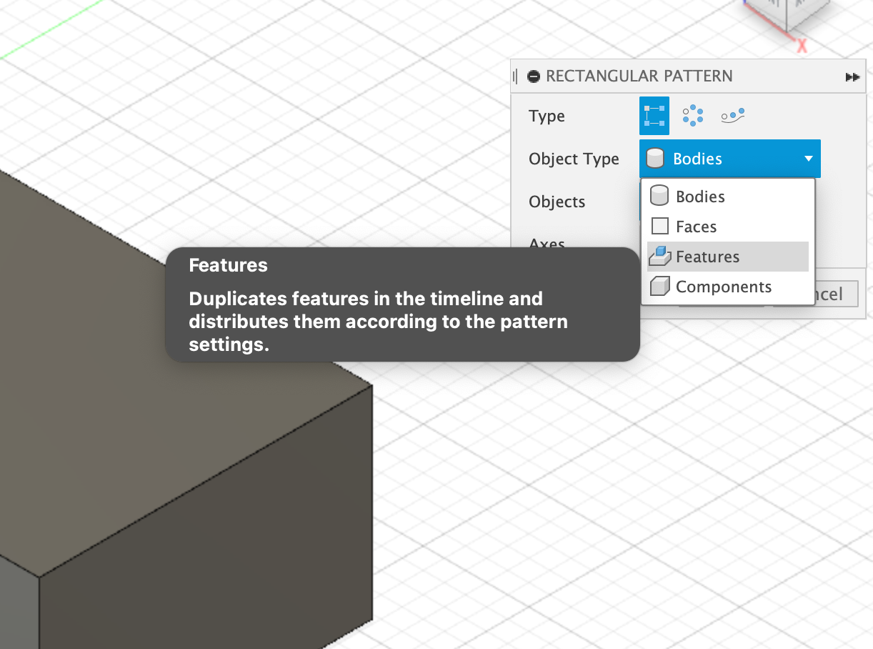
Rectangular Pattern Feature There is both one for sketches and models, recommended to avoid the sketch tool. Keeping your sketches simple, will make it easier to make a fully parametric model.
- Using the Rectangular Pattern Feature:
- select tool in Solid tool bar.
- it will default to BODIES, but FEATURES will allow you to select the EXTRUDE feature in the parametric timeline.
- when selecting a feature in the parametric timeline, the object it is attached to will shine up in blue.
- use the directions selecter (in mine its called axis selecter) to define the directions of the pattern (in this case cylinders on cube)
- define the axis you want to display pattern on
- drag them out with the arrows so you can see it in motion when changing the values
 (image of pattern feature bar)
 (object shine when selecting feature in parametric timeline)
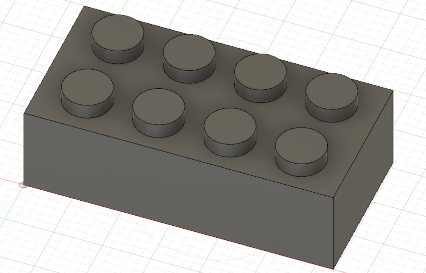 (Pattern Feature Done)
- Use the Shell feature to make the cube hollow from the bottom up.
- It can be found within the Modify menu in the tool bar.
- you can select faces or bodies (in this case I am using faces)
- define the inside thickness (in my case 1.49mm)
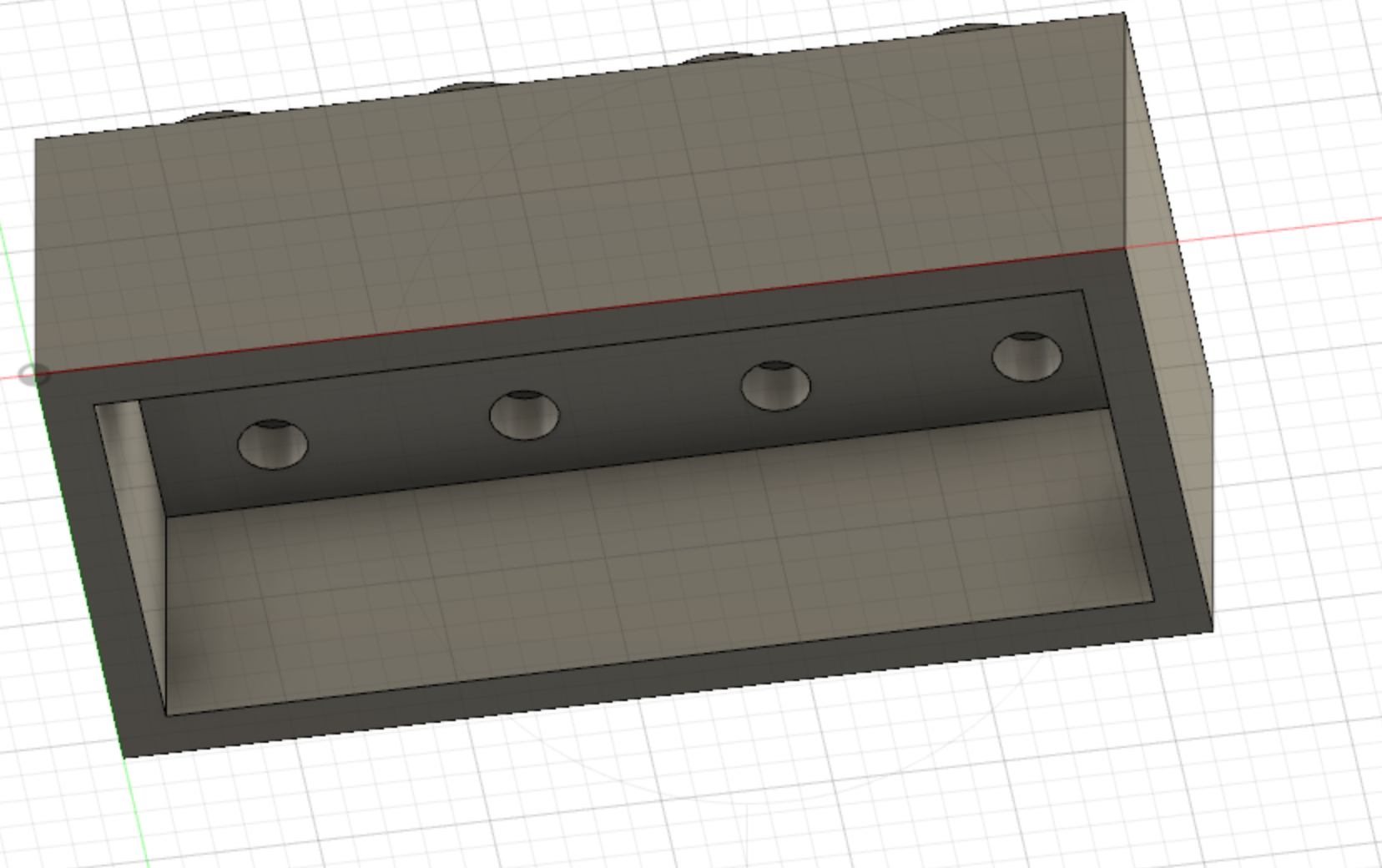 (image hollow bottom)
- You can make a new sketch by right-clickin on a planar face, and selecting CREATE SKETCH.
- activate the LINE COMMAND in the toolbar.
- you can select the CONSTRUCTION option in the linetype, for making a line for reference purpose only.
- if you are looking at the model from an orthographic view, you can use the existing geometry to make new lines
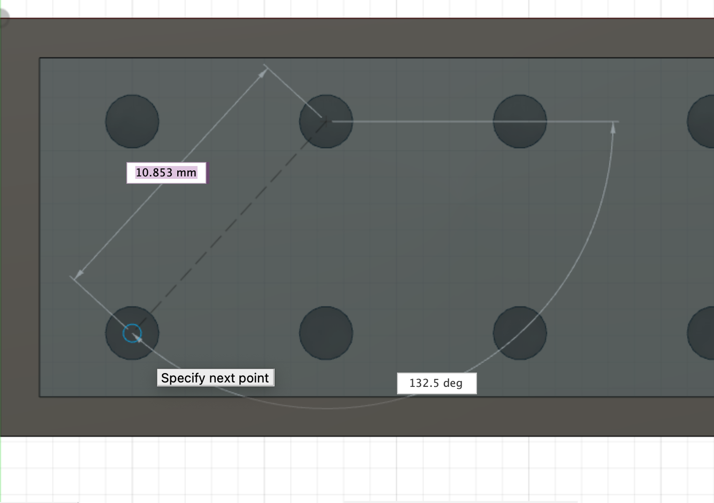 (image of center point to center point cylinders)
- find the center point (when the blue triangle appears) and draw your new circle. Make sure CONSTRUCTION is now turned off.
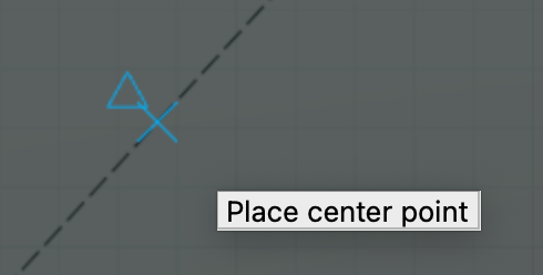 (center point of diagonal line)
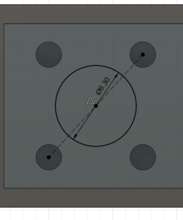 (image of new circle at bottom)
- Extruding sketch with two defined walls
- Use the OFFSET SKETCH TOOL in the toolbar
- Select the sketch (in my case circle at the inside of my cube) and define the thickness of the wall you want
- Use EXTRUDE IN SOLID toolbar and define the height
- Use Rectangular Pattern Feature to add another extruded cylinder.
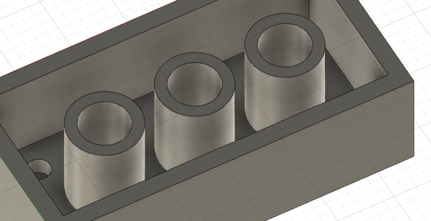 (image 3 extruded cylinders)
- Adding FILLET or rounded edges to sharp edges of model
- activate FILLET command from the MODIFY dropdown bar
- select the faces/edges you want to add FILLET to
- define the intensity of rounded edges and press OKAY
This where there the tutorial ends. I feel I have some understanding of the workflow now, and will continue developing in project-based pages.