Making an acrylic box for circuit boards
After I learned how to work with user parametrics, I followed the steps below to design this box in Fusion 360.
I followed this tutorial
Step 1: Establishing the user parameters
My variables:
-
Material thickness: 3mm
-
PressFit snug joint value: 2.7mm
-
Box height: 60mm
-
Box width: 70mm
-
Box depth: 40mm
My parameters:
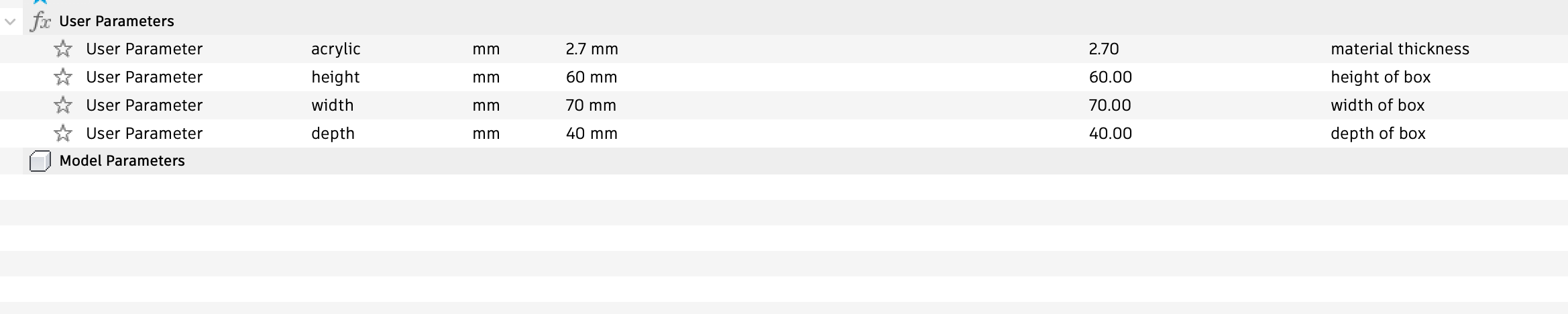 image of user parameters set up
Step 2: Creating the base
-
Start a new component and call it base
-
Start a new sketch, on the ground plane
-
Create a center rectangle by starting off at the center point of your viewport, and give it the dimensions depth and width like so:
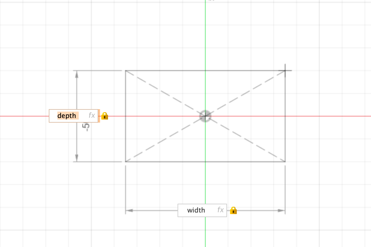 (image of dimensions rectangle 1 defined)
Step 3 : Finger joints on base
-
Before finishing the sketch, we are going to make a couple more rectangles that will serve as the finger joints.
-
On the top edge of your rectangle, draw 3 more. (do not worry about sizing just make sure they are lying on this top edge)
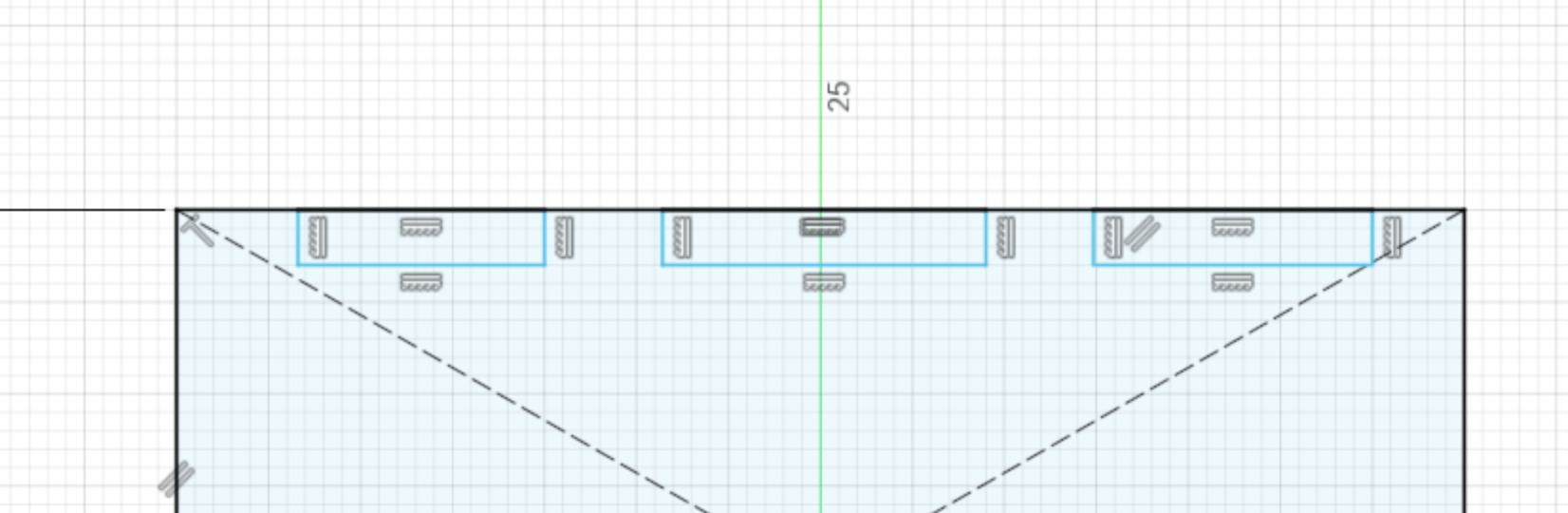 (image of 3 rectangles on top edge base)
-
Select the line tool, and make lines within the interval spaces between these 3 rectangles, as shown below. Make sure these lines are perpendicular.
-
using the select option and holding shift, select all these new lines and within the SKETCH PALETTE on the right, make the LINETYPE into CONSTRUCTION lines.
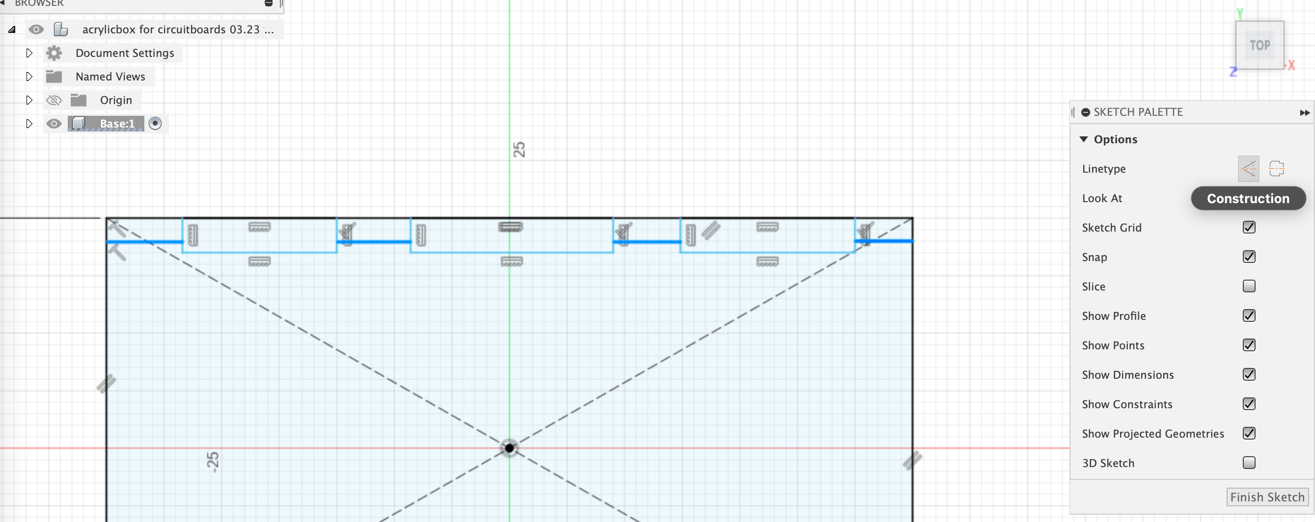 (image of construction lines at midpoints)
- We now want to make all these construction lines equal in length. Click on the EQUAL button on the top tool bar (it looks like the dutch flag).
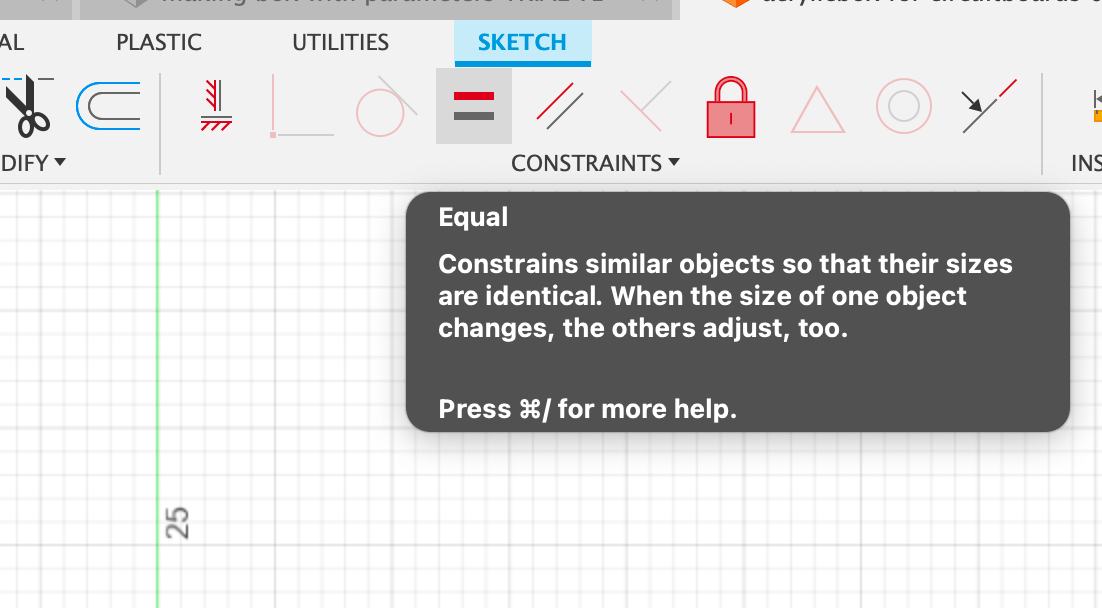 (image of EQUAL button in toolbar)
-
Alongside the construction lines, we want the vertical length of each rectangle to be the same. Click on the bottom edges of the rectangles (hold shift) and click on EQUAL.
-
Select the SKETCH DIMENSION tool (or key d) to make the depth of the three rectangles the previously established parameter of material thickness, in my case acrylic.
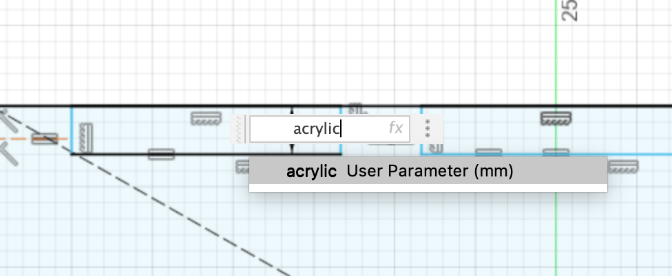 (image of applying acrylic thickness parameter to depth of rectangles)
- Continue with the SKETCH DIMENSION tool and give the bottom edge of one of the rectangles a round numbered length, which will automatically apply it to the other squares. (Mine was already around 16.666666667 but I changed it to 15mm eventually, so that the shorter edges could also match this)
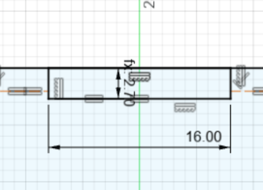
(image of applied sketch dimension to bottom edge of one of the joint rectangles)
Step 4: Mirroring finger joints to bottom edge of base
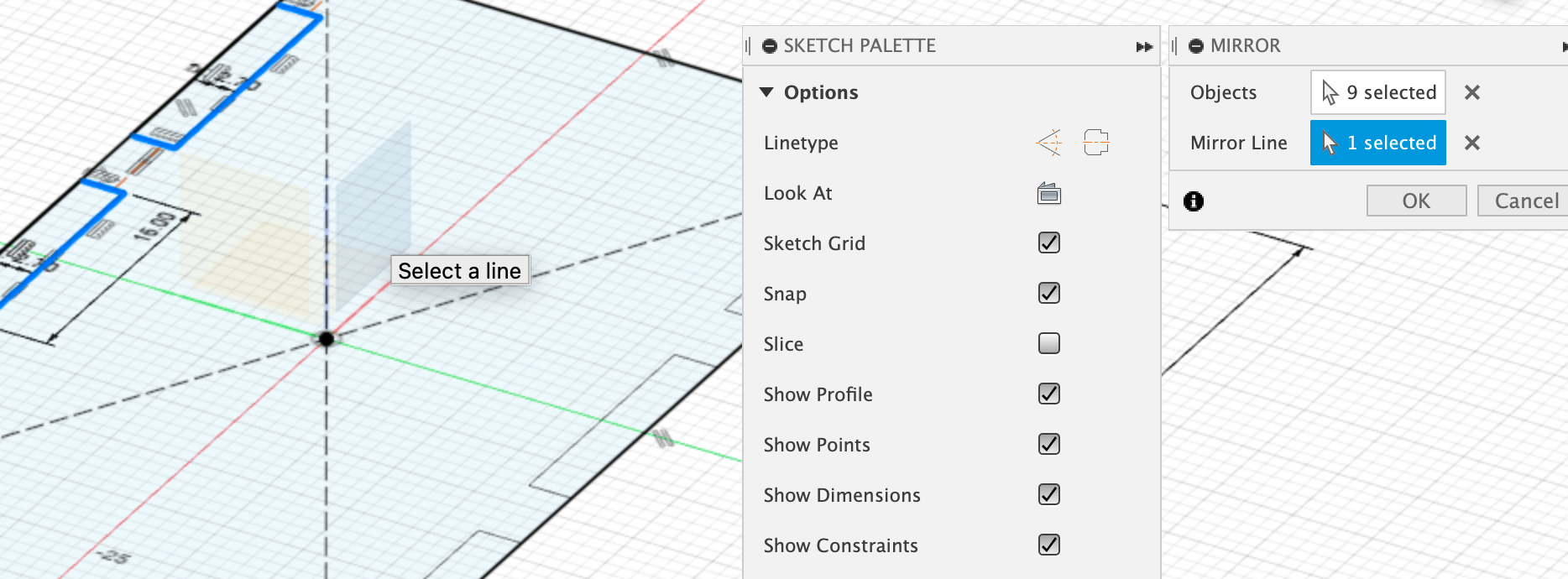
- Select the MIRROR tool in the top tool bar (on the left of SKETCH DIMENSION), which will open a new window. Select all the edges of the three rectangles, (you don’t have to hold shift) and once you have done so, you can see how many objects you have selected in the new window.
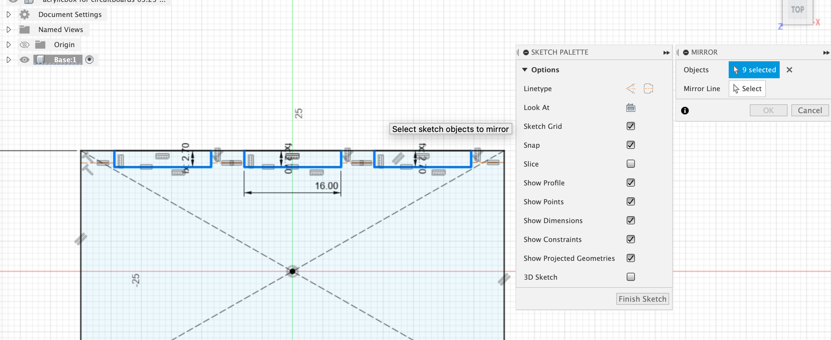 (image of edges selected for mirroring)
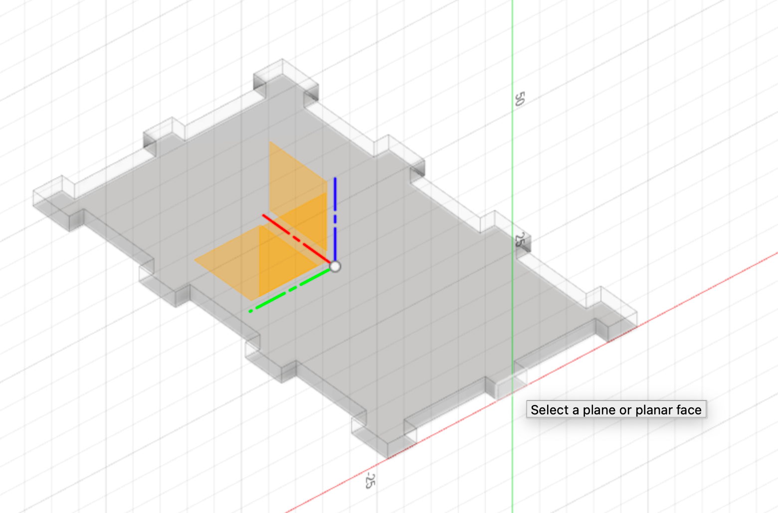
- Click on the MIRROR LINE below this view, and you are going to want to select the origin plane for this. Orbit your view slightly so you can see the z axis. If you can’t see the origin plane, make sure the ORIGIN is made visible in the right browser of components. Once you select the origin plane, you can see an outline of where the objects will be mirrored to.
 (image of mirroring option with origin plane selected as mirroring line)
Step 5: Repeating step 3 for the right edge of the base rectangle
-
When starting to sketch the three rectangles for the finger joints, double check that CONSTRUCTION isn’t selected within the SKETCH PALETTE next to LINE TYPE.
-
Remember to then reselect the CONSTRUCTION line type when you are drawing the lines for the intervals of the rectangles.
When finishing all the finger joint sketches on the base, I realized that this would eat from the space within the box (3mm at each side), so I might have to make the width and the depth of the box itself slightly larger. 3+3=6mm should then be added on both parameters
 (image of adapted parameters)
Step 6: Extrude base
-
Click on FINISH SKETCH at the bottom of your Sketch palette.
-
Select EXTRUDE in the SOLID toolbar, (or key E) and select the middle base face.
-
Give it the value of your material thickness (in my case acrylic as set in parameters)
 (image of extruded base)
Step 7: Making Side 1
- Activate the top level component in your browser, like so:
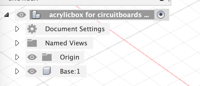
(image of browser view with top component active)
-
Create a new component and give it an identifiable name (e.g Long side 1)
-
Create a sketch, and select one of the fingerjoint faces like so:
(image of joint face selected)
It will orient the view like this:
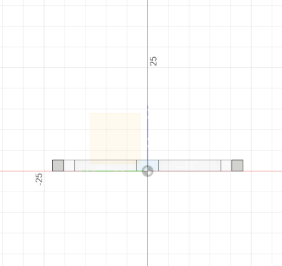 (image of YZ view)
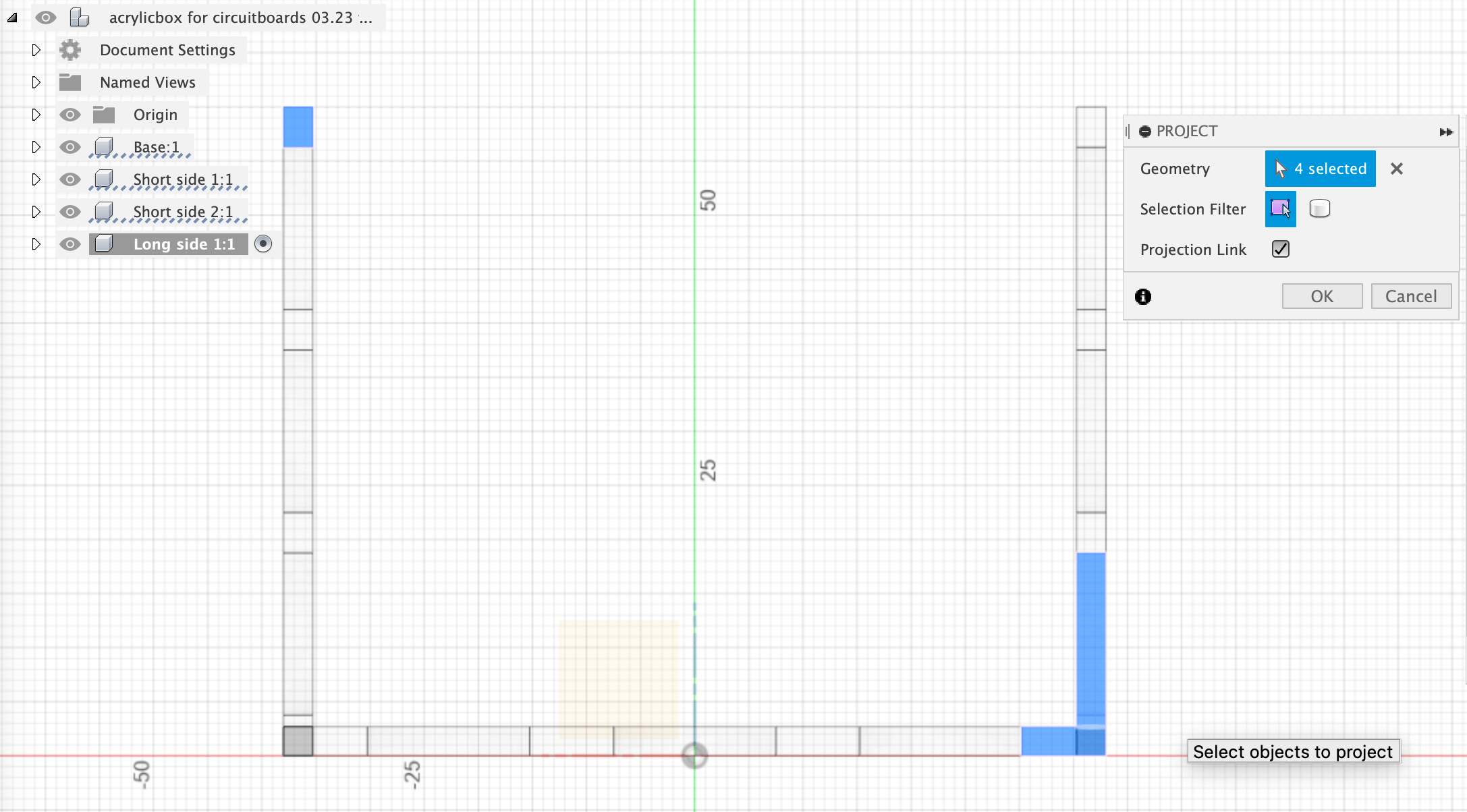
- Press key P to project (or find it in the drop down menu CREATE) and select all the faces on this side and click OKAY in the new window.
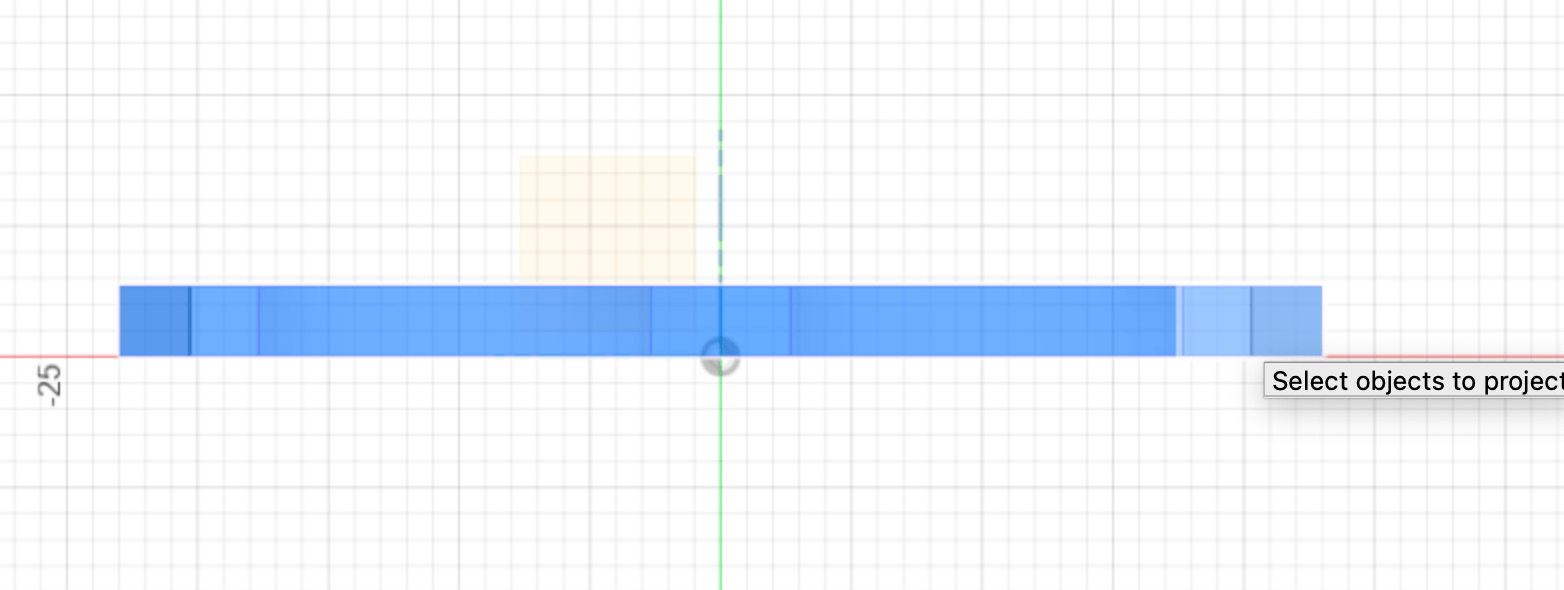 (image of selection faces YZ view for projection)
-
Create a new two-point rectangle and allign it with the ends of the selected elements.
-
Use the SKETCH DIMENSION tool to define the height parameter to this rectangle on its vertical sides.
Since the projection made the fingers joints on the bottom horizontal edge, we can continue by making the finger joints on the vertical edges. For my design, the height is about the length of the width, so I will make 3 rectangles again. See if this applies for you as well, if not you can also do 2 instead.
-
Make the desired number of rectangles on the edge and make lines between each midpoint, like we did in step 3. Turn them into construction lines, and make them equal.
-
Select the bottom finger joint lines and make them equal in length.
-
Assign your material thickness parameter to the width of the finger joints.
-
Assign the width to the bottom finger joint lines as the same as you gave the previous ones (in my case 15mm)
Your vertical axis will look something like this:
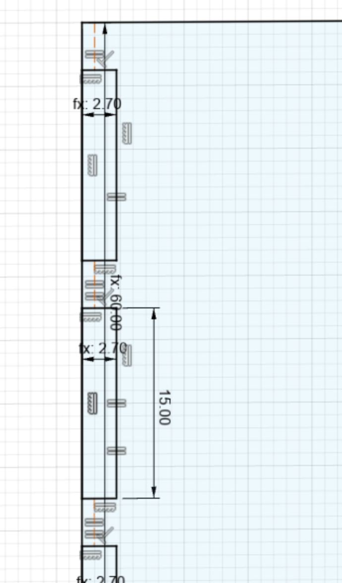
(image of vertical axis diameters)
-
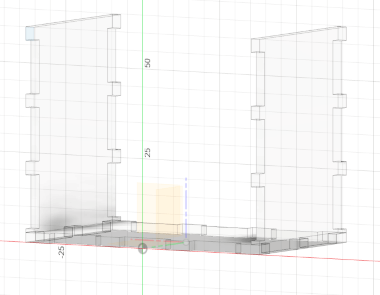
Mirror the objects you just made, onto the other side of the main rectangular side, using the MIRROR tool on the orientation plane. Make sure to select all the components you intend to mirror.
-
Finish sketch, and extrude inwards (negative value) the value of your material thickness.
Step 8: Making Side 2
-
Activate the top level component again.
-
Create a mirror by selecting MIRROR under the CREATE dropdown toolbar.
-
In the MIRROR window, select COMPONENTS and select the side you just created.
-
Select the origin plane as the MIRROR PLANE
I noticed that parts of my side 1 hadn’t extruded 2.7mm alongside with the rest of the component, so I went back to when I did this in the timeline on the bottom left of my viewport and right clicked on it. This allowed me to adjust the features, such as include those I hadn’t included before.
Step 9: Making Side 3
-
Create a new component and give it a recognizable name.
-
Start a new sketch, and select on the the finger joint faces, that is facing where we will start the new component.
 (image of positioning new sketch for side 3)
- Press key P and project two outer corners onto the this new sketch.
 (image of projection onto sketch 3)
-
Make a two-point rectangle that spaces over from Side 1 to Side 2, making sure it alligns with the edges. Finish Sketch.
-
Extrude the main new face and the projected elements, and assign it your material thickness parameter, making it negative so it extrudes inwards.
-
After this, make the top level component active. We will make Side 3 frame around the other faces. In your top toolbar, select COMBINE above MODIFY. Within the new window that will appear, choose Side 3 as the Target body, and the other 3 sides the Tool bodies. Choose cut as OPERATION, and tick the box for keeping the tools.
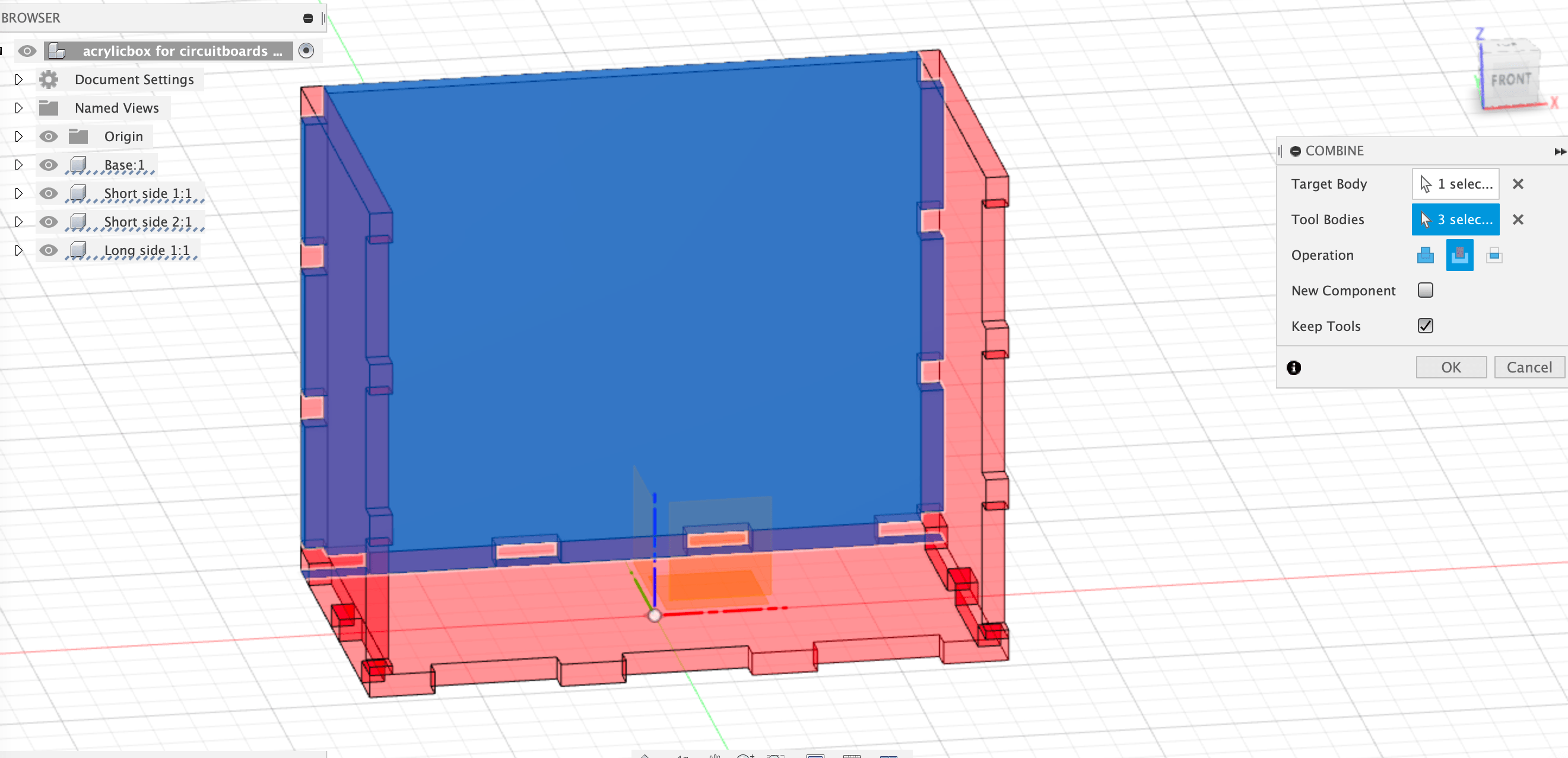 (image of selection COMBINE bodies)
Step 10: Making Side 4
Like we did before, we will mirror this new component to make a new side.
- Select MIRROR tool and choose Side 3 as OBJECT, and origin plane as the MIRRORING PLANE.
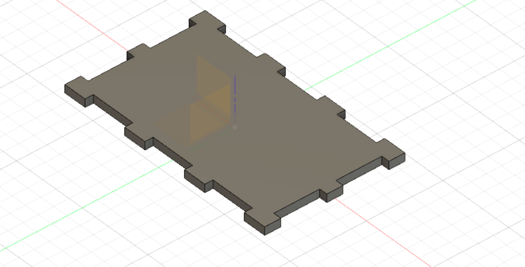
We now have 5 sides, including the bottom base. In order to check if all of the finger joints are correctly interlocked, there is a tool to view this well in the INSPECT dropdown menu called DISPLAY COMPONENT COLORS.
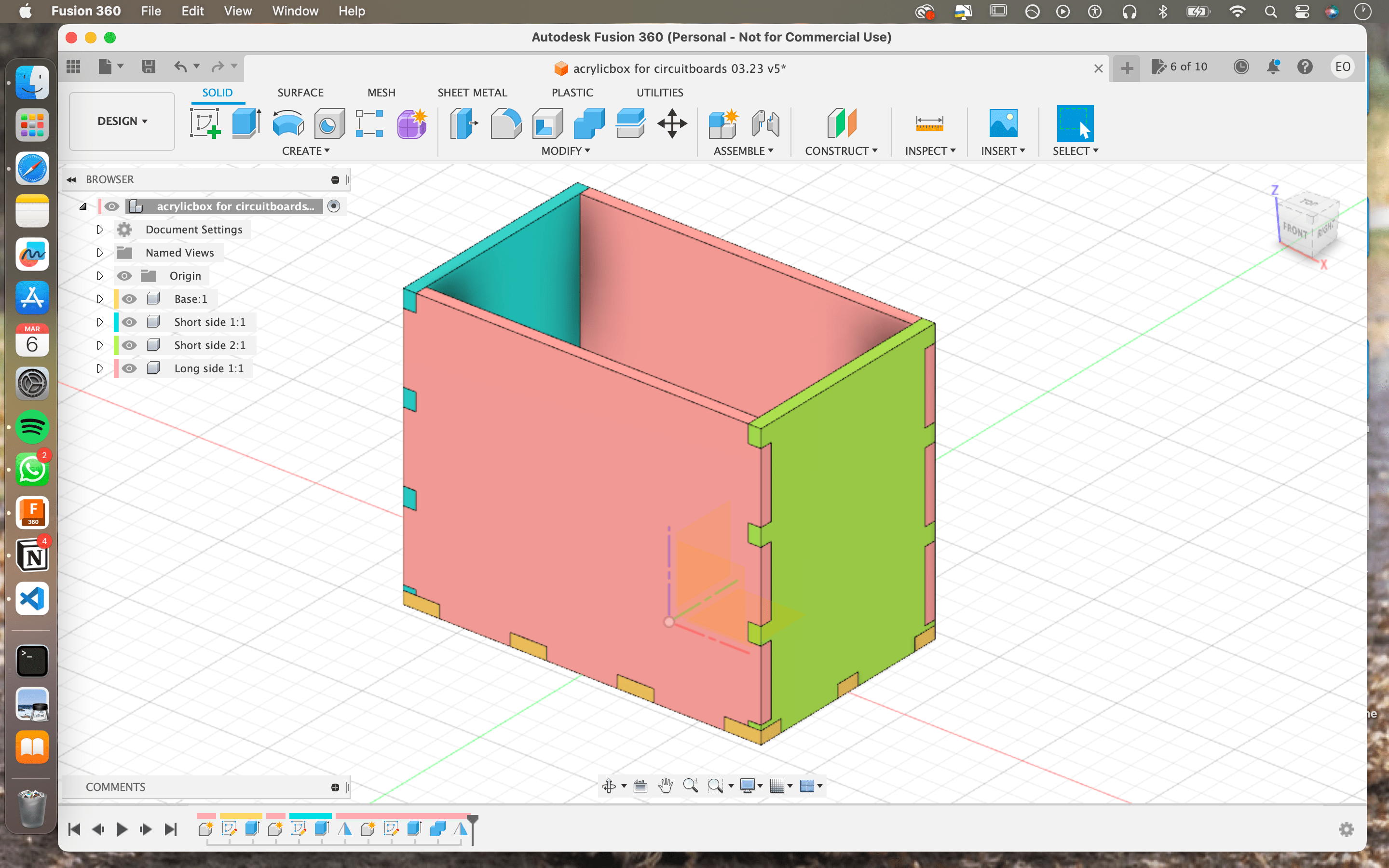 (image of box in component colors)
Step 11: Making a lid
For this box, I want to be able to close it and keep the components stored safely. I had been thinking on how to make a simple lid that works on a small box and is sturdy. After talking to Maria and Michelle, I decided on a slide in lid.
(image of sketch of lid design)
Because my design within Fusion 360 is set up with parametrics and a lot of mirroring/equalized dimensions, I tried making one of the sides shorter but this influenced all the other sides as well. I am now thinking of making visible lines of where I want to cut off some of the height of one of the sides, and engrave on 3 others, and then assign these tasks within Lightburn so I don’t have to interrupt the setup I have in Fusion360.
-
Make the top component active, and make a new component.
-
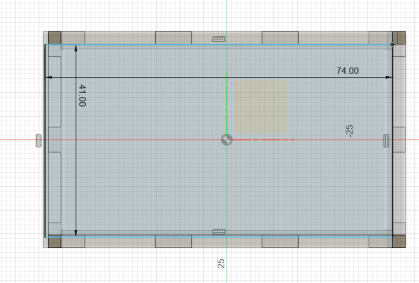
Make a 2 point rectangle, on a top face of one of the components, so it lies where the lid will go.
-
Give it the dimensions of 43h (40 + 3mm for material thickness at the front) 70w, + 1mm on each side that will fit into the pockets on Side C, D, and E.
-
Extrude it for 3mm (material thickness)
 (image of the lid done)
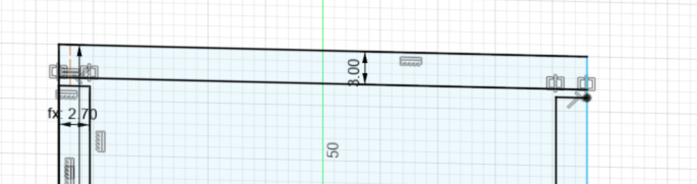
CUTTING
I will cut 3mm (thickness of material) off of Side A so that there is space for the lid to slide in.
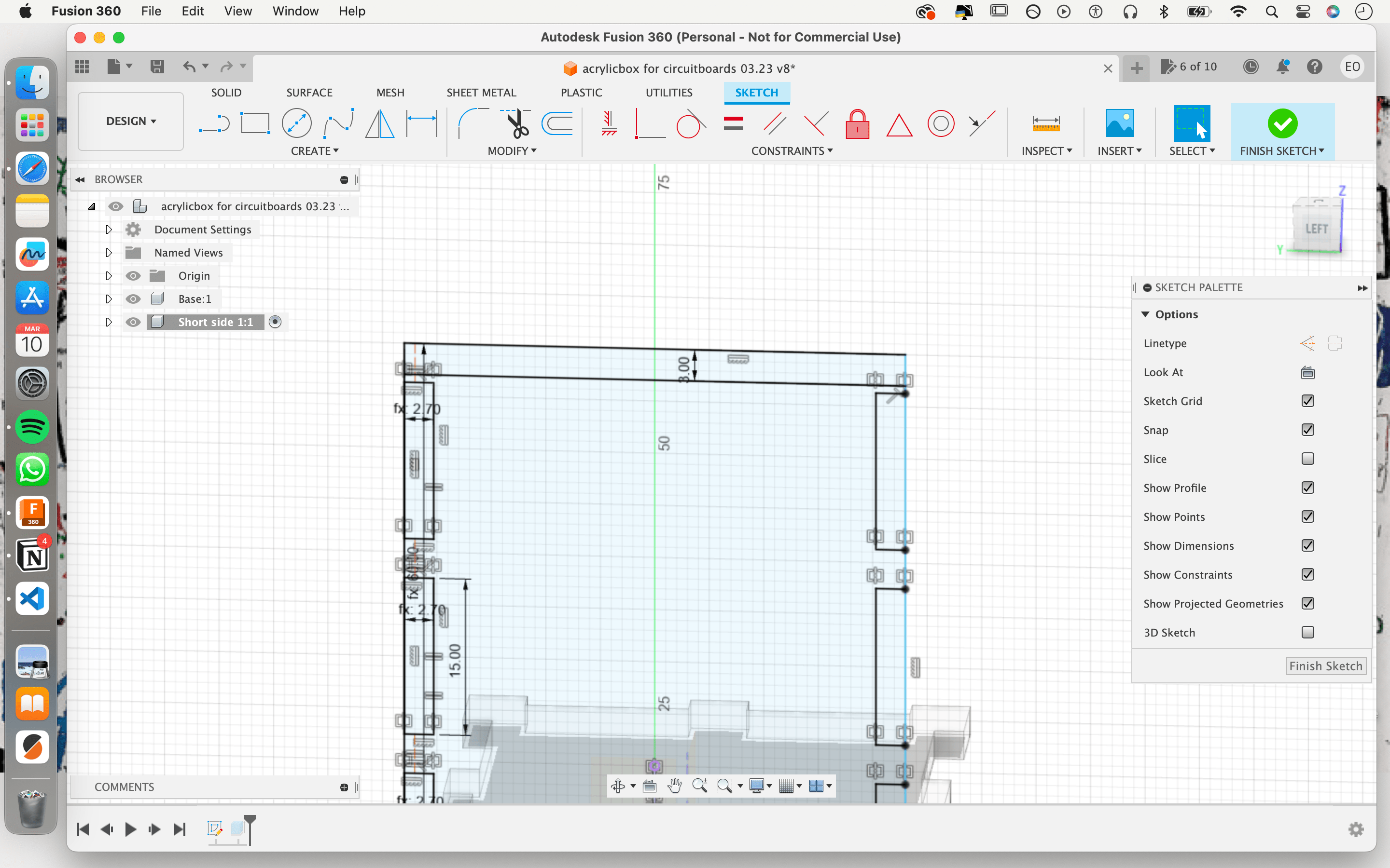 (image of 3mm distance drawn line)
-
make a new component on Side A, and give it a name like Cutting Line
-
new sketch, a two-point rectangle on the exterior face of Side A
(image of cutting line sketch on Side A)
-
assign a sketch dimension between the top edge of Side A and the bottom edge of this new sketch of 5mm
-
Extrude the cutting line by 1mm
 (image of rectangle component on Side A)
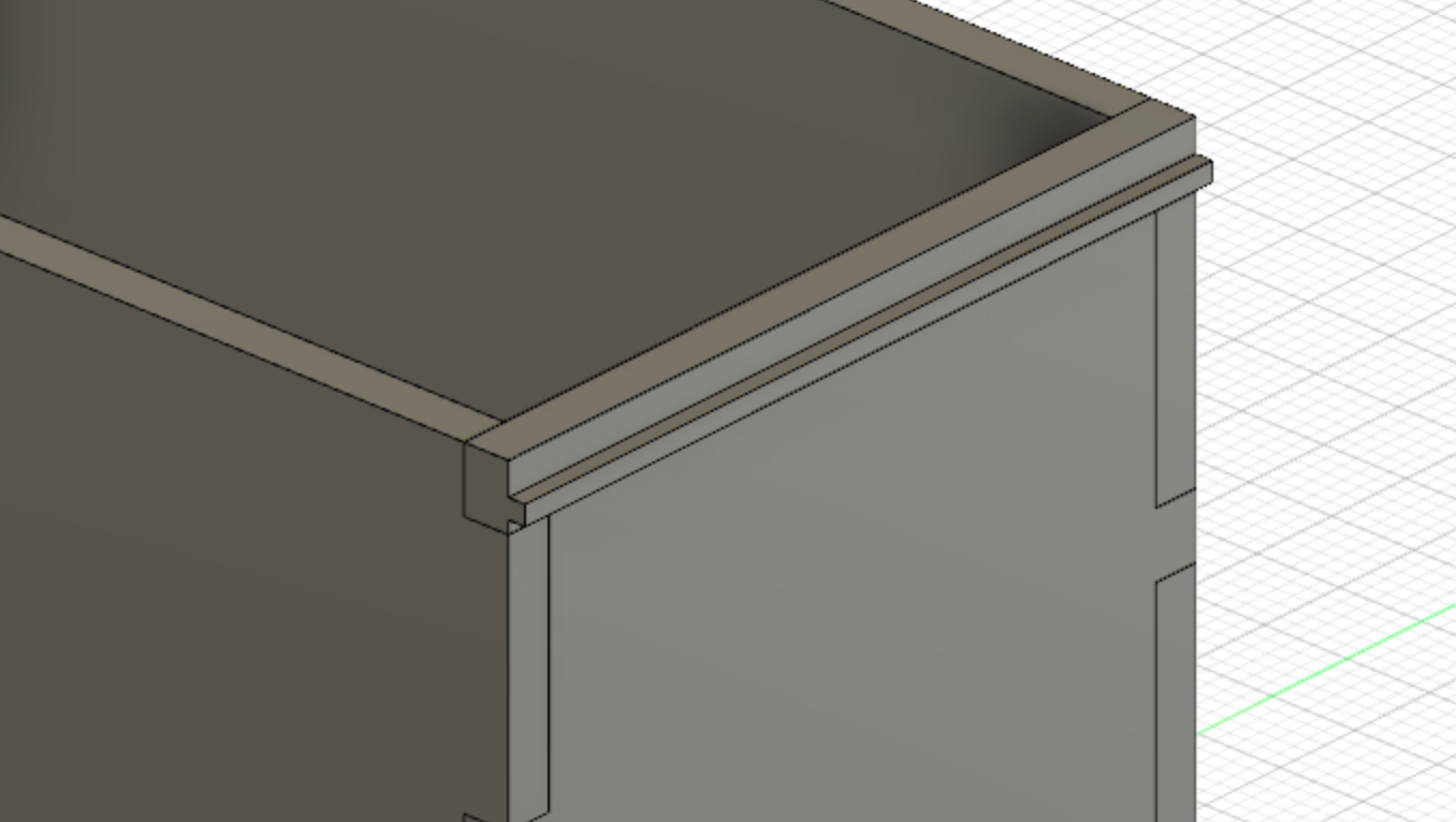
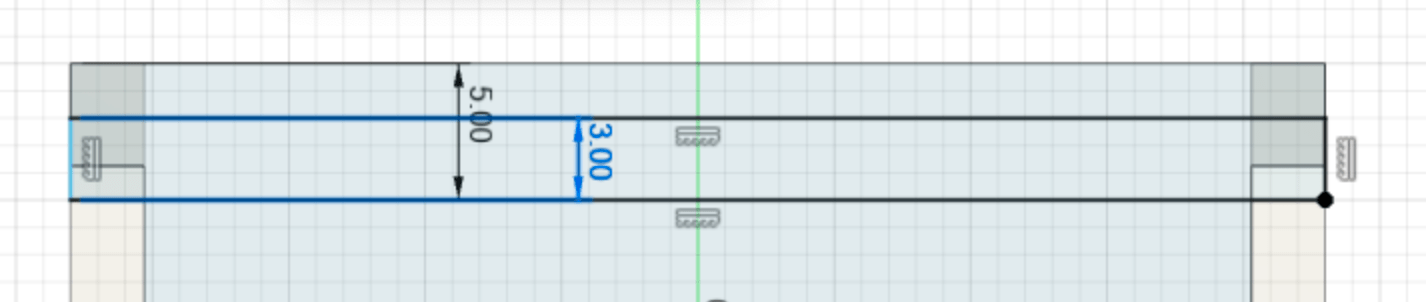
ENGRAVING
In order for the lid to firmly sit against three other sides, I am going to engrave a line on these 3 sides to create a slight pocket. I am not sure exactly how much this will eat from the material depth wise (dependant on speed/power) so I will estimate how much wider the lid should be, but might have to adjust the design and cut it again.
- Make a rectangle sketch on the inside of Side C, D and E, 5mm from their top edges and a height of 3mm (to match the thickness of your material)
Power: 40 Speed: 200
Exporting for Lightburn
-
I have previously exported DXF files from Fusion360 before, but there were only a couple of sketches so the process was simple. I now have to figure out if there is a way to do this more efficiently for this design.
-
I want to lay all the components flat on the origin plane, and there is a couple of ways to do that. the ARRANGE feature is unfortunately not available for the Personal Use version of Fusion360.
Step 1: NESTING THROUGH JOINT FEATURE
- perfect for simple models
-
Will allow you to position parts in their desired position, so it is also possible to position them all on the same planer face
- Activate the JOINT command in the top toolbar (not AS-BUILT JOINT)
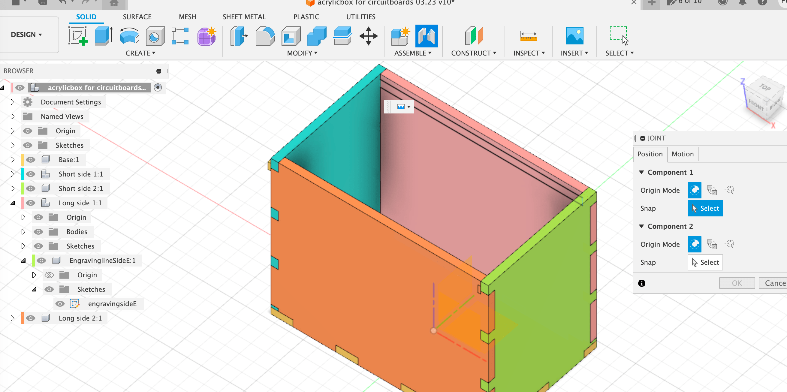
(image of toolbar JOINT command selection and new window)
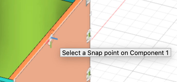
- Set the JOINT ORIGIN by selecting the corner or center of a straight edge. Make sure the selector is facing sideways, otherwise it won’t rotate the way we want.
(image of orientation joint selector on face)
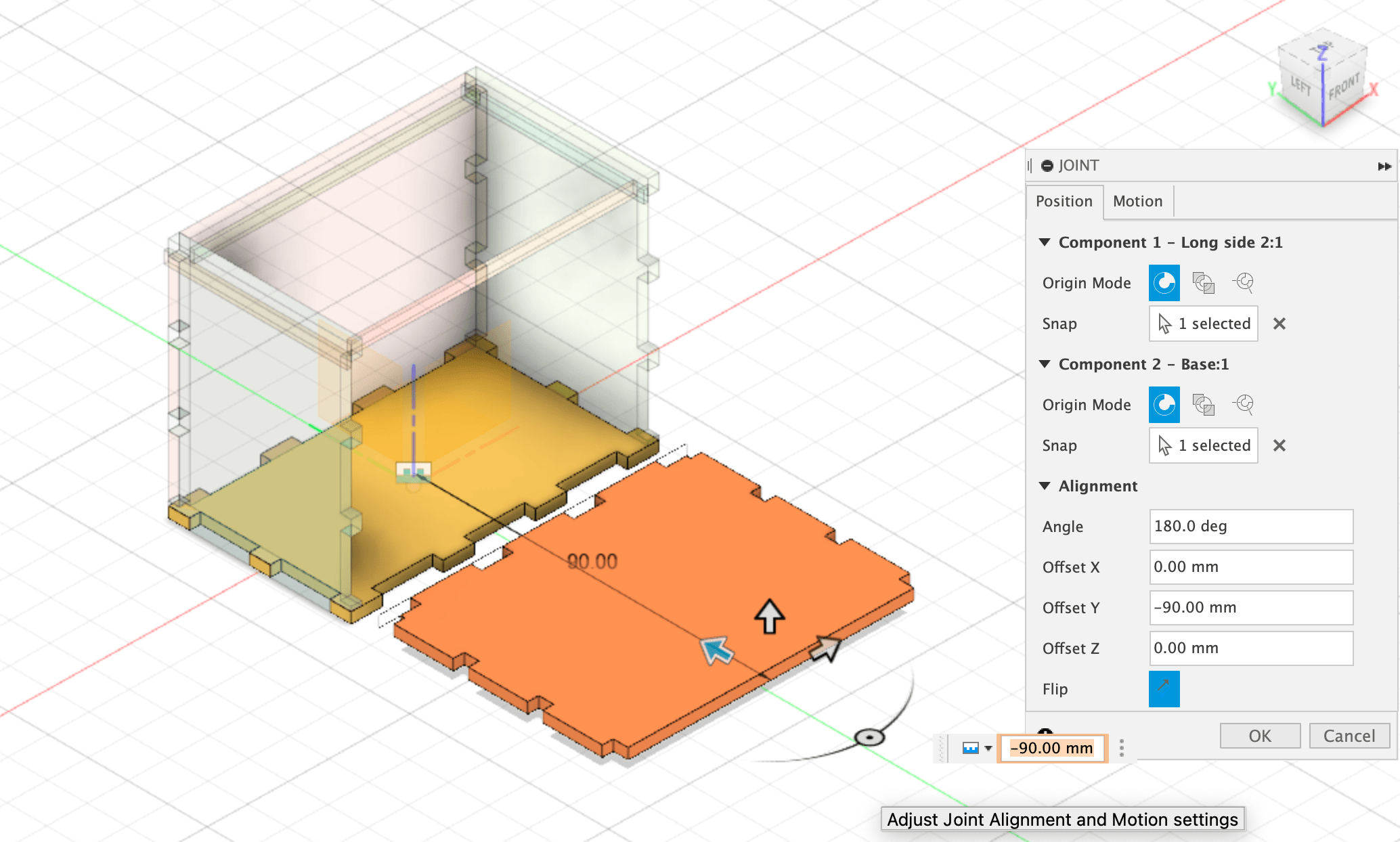
- Turn on the ORIGIN folder in the browser, so you can make that the second joint origin
(image of first side nested)
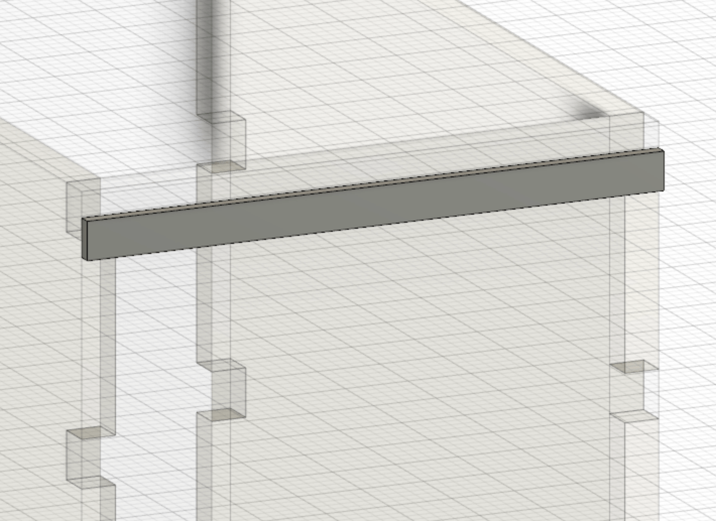
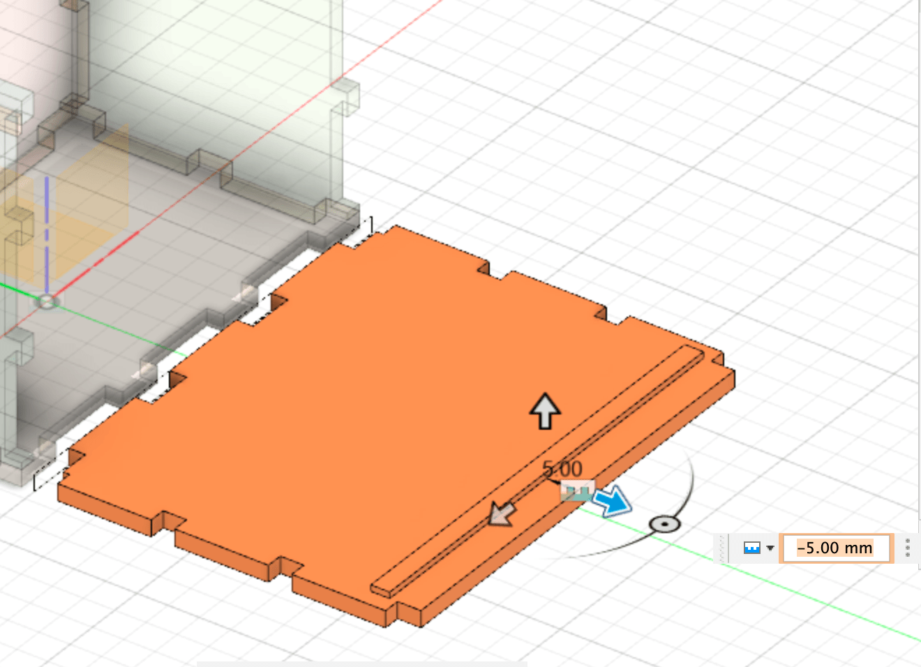
- With the engraving and cutting lines, I used the component on which it lies as the second joint origin, and then gave it a Y offset of -5 (or 5 depending on where the top of your component is) to make sure it lies on it and not at the same Z axis level.
(image of engraving line nested on component side)
- Repeat this until all of your components are lying on the origin plane. Double check that they are all on the same level, this is important for later.
Step 2: PROJECT ONTO NEW SKETCH
-
create a new component
-
Start a new sketch and use the origin plane as its start
-
Under the CREATE dropdown menu, select project.
-
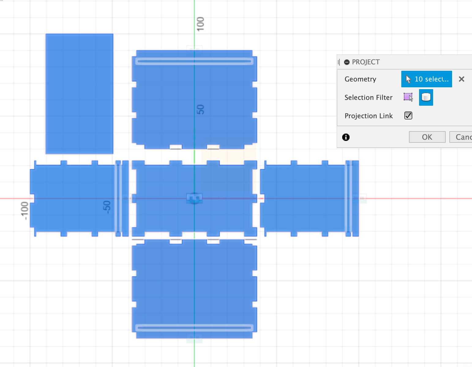
Within the new window, choose 3D bodies as selector and select all components.
-
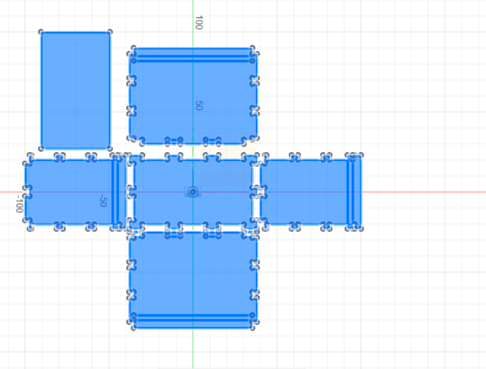
Make all other components invisible in the browser, and check if this projected sketch was successful and if all elements are closed sketches, like below. They will all highlight blue.
 (image of projected sketch of all components)
- Find this new sketch in the browser, and right click on it. Save as DXF.
Your box design is now ready to be cut! To learn about our lasercutter and how to use a design like this, see this page
RETURN TO THE DESIGN
(image of outcome box cut)
There are a couple of adjustments I need to make to my design
-
Although I used what I learned from my PressFit, the finger joints aren’t snug enough. I believe I didn’t apply the Kerf correction sufficiently to my design.
-
The lid can be slightly wider to fit deeper into the engraved lines on the sides.
Offset finger joints
After looking at the outcome of the box and talking with some people, I realized which diameters need to apply Kerf correction to. I did the following:
- I had previously changed my material thickness parameter to the value I got from my PressFit comb, but this only affected a couple of values and also applied it to both the fingers and the pockets of the joints. I reversed this, and instead added a new parameter of 0.3mm.
(image of new offset parameter)
- I started working on the sketch of the base of my box, by editing the feature in my timeline. I soon realized that when extruding this would have implications on all the sides seeing I worked with projecting and mirroring features. Instead, I kept it the same and went to the last sketch I made, which projected all my components when nested together. This way, I was in more control over which sketches I was making changes to.
-
So, going to the base within this sketch, (within the FOR LASERCUTTING component) I started with the first finger socket and created an offset. You can find this in the tool bar but the key command is ‘o’.
-
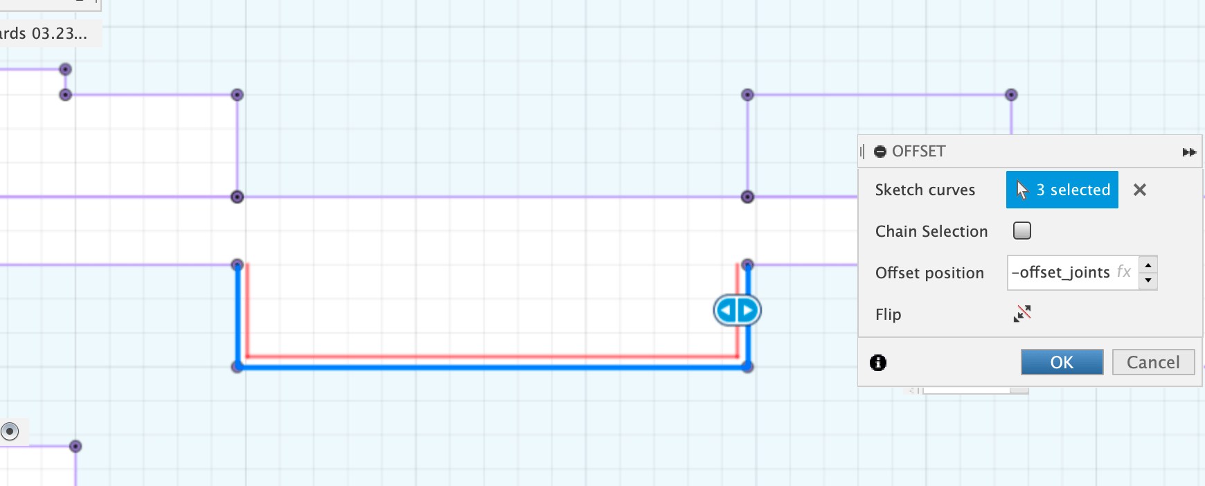
Within the pop up palette, you can choose the lines which you want to create an offset for. Apply the parameter we made, “offset for finger joints”.
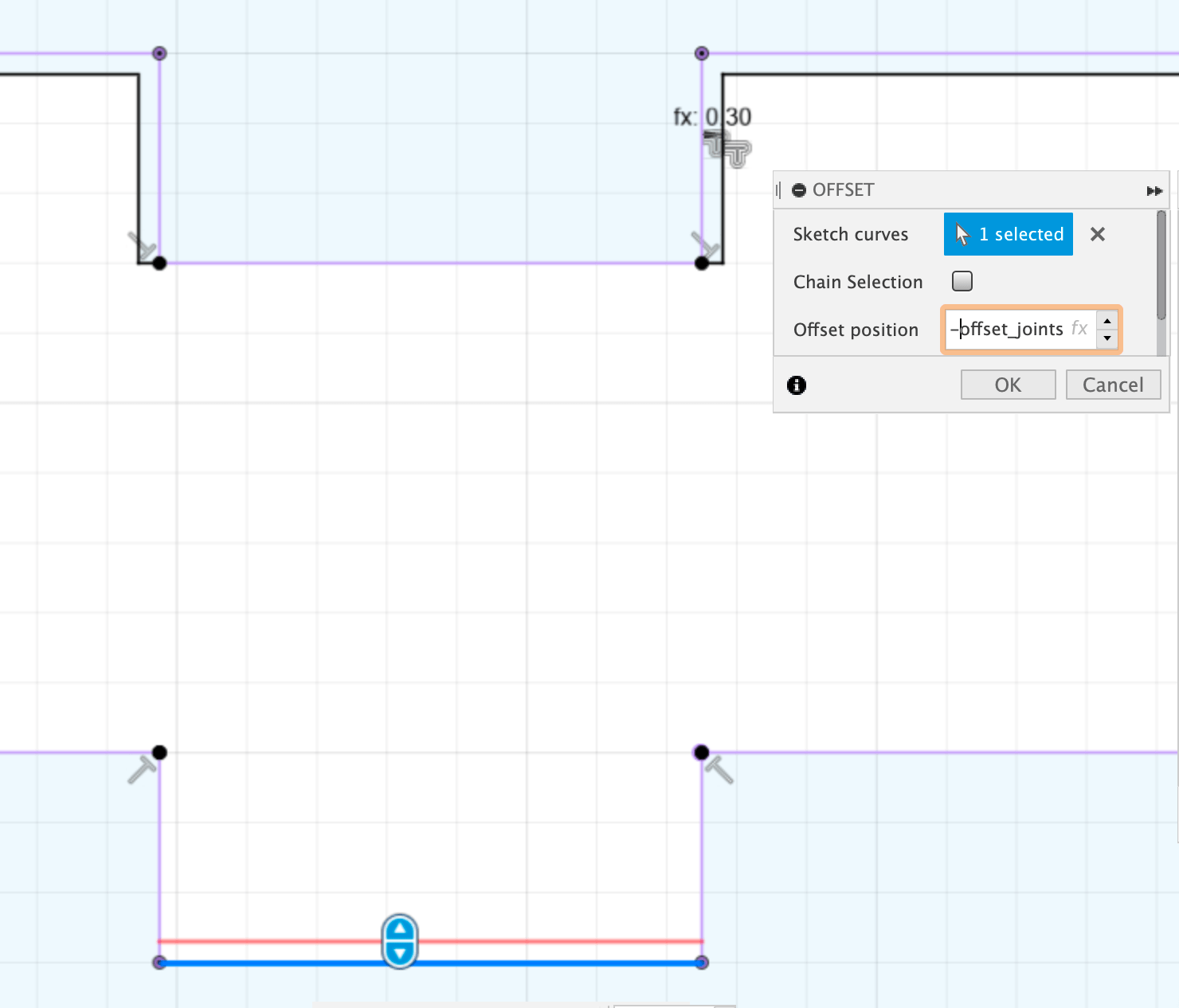 (image of parameter applied to offset for socket)
- Once I did this for all the socket joints on my base, I looked at where all the sides fit into this base and how this offset would influence their fit. As you can see in the image below, the offset on the x axis of the above finger joint will make the fit more snug. However, this does not influence the vertical fit so I added the offset on the y axis of the socket.
 (image of finger and socket offsets applied)
-
I continued going through the design like so, looking at the fingers and sockets as pairs.
-
Sometimes if the offset is extruding like the one below, not all the sketch lines will intersect yet. This will lead to an open shape and so the sketch will not be filled in light blue. Make sure to make interlocking lines when necessary.
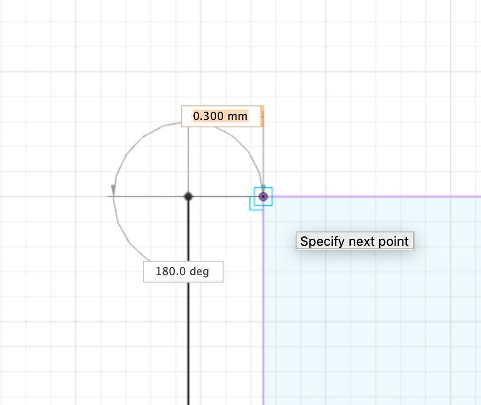 (image of extra line for closed shape)
RESOURCES
https://www.youtube.com/watch?v=Ay0EKXvW1GE
useful for lasercutter at KABK, through Illustrator
https://www.youtube.com/watch?v=y50jrXRwvZ0
plug in for automated Kurf correction:
https://www.youtube.com/watch?v=0pGyZtcwqIk
nesting:
https://www.youtube.com/watch?v=IDp_EAHPdvY
nesting add-on for Fusion360 personal use:
https://www.youtube.com/watch?v=BmuxxvIU2XA&t=0s
Lay parts flat with Arrange feature:
https://www.youtube.com/watch?v=PN4bd4rr4z8&list=PLrZ2zKOtC_-B_HAKUEXhaHyK-2ksfFx2K&index=1
Mapboards add in (14USD):
https://apps.autodesk.com/FUSION/en/Detail/Index?id=7055850008078104945&appLang=en&os=Win64
Joint Feauture as way of nesting :
https://www.youtube.com/watch?v=yneagO-i6mw&list=PLrZ2zKOtC_-B_HAKUEXhaHyK-2ksfFx2K&index=3&t=5s